
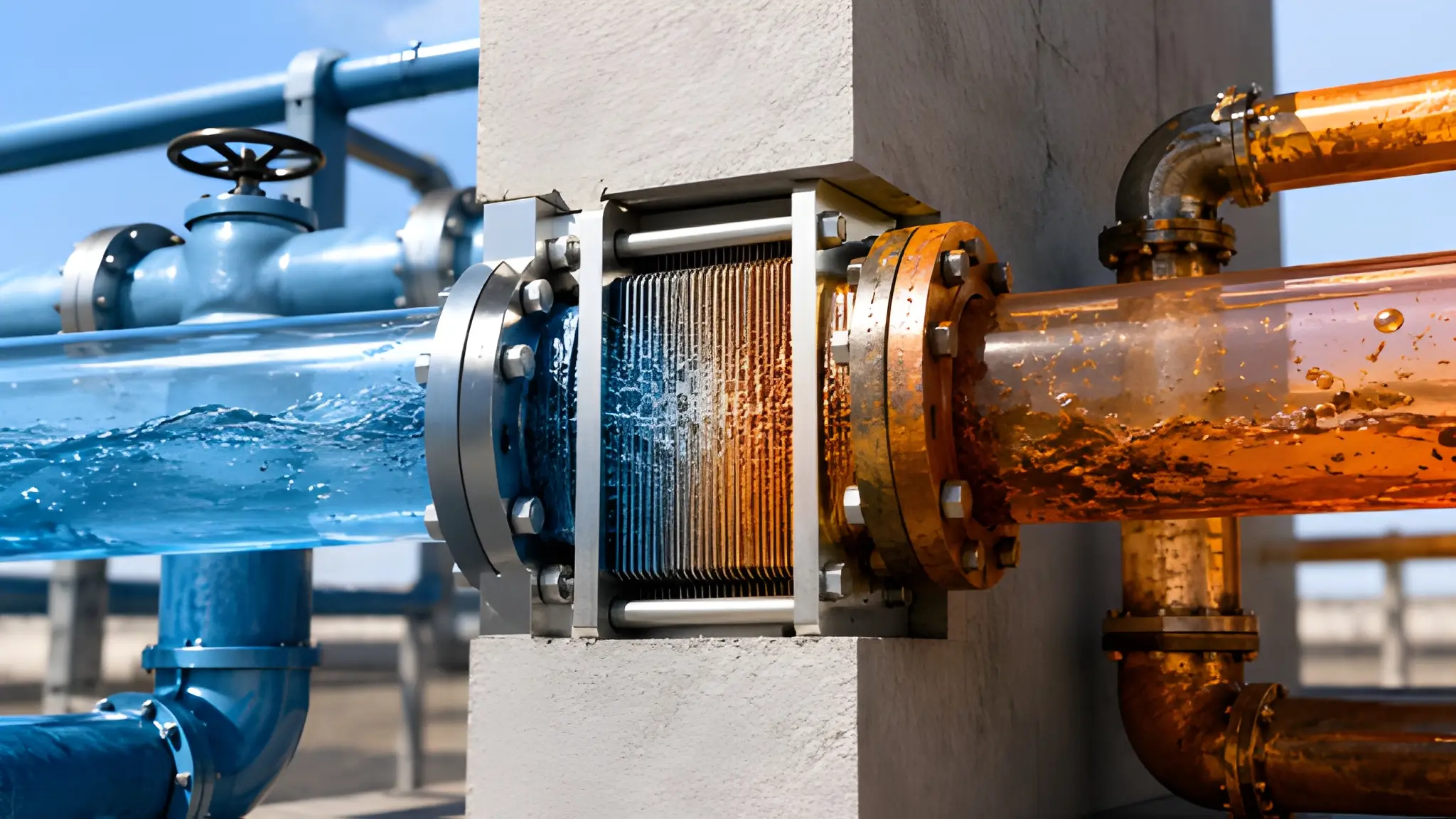
A facility water connection may look like the obvious boundary between building infrastructure and liquid-cooled computing, but the real engineering boundary sits inside the coolant distribution unit, where the heat exchanger keeps two fluids physically apart while forcing them to exchange heat. That distinction matters because the heat exchanger carries thermal, hydraulic, and contamination consequences that a wall penetration does not directly control. A well-designed penetration can remain intact while exchanger fouling, scaling, or corrosion reduces heat-transfer performance, while an exchanger integrity failure can compromise separation between the primary and secondary circuits. The approach temperature provides one of the clearest operating signals because it reflects how effectively the exchanger transfers heat under actual flow and temperature conditions. When that temperature gap widens at comparable load and facility-water conditions, operators gain an early indication that the thermal interface has changed.

From an operational perspective, the exchanger should therefore receive the same attention as pumps, valves, sensors, and control logic because its condition directly influences the stability of the technology cooling loop. A rising approach temperature can result from fouling or scaling, while a pressure differential across the exchanger can influence the direction and severity of any leak if the physical barrier develops a defect. Monitoring supply and return temperature, flow, and pressure on both sides creates a more useful diagnostic picture than relying on a single leak alarm after the event. Equipment specifications should establish acceptable operating envelopes for these parameters and define what constitutes a service intervention before cooling performance reaches a critical threshold. Contract language also needs to distinguish normal performance degradation from a failure attributable to exchanger integrity, installation quality, fluid chemistry, or operating conditions outside the agreed envelope.
Water Chemistry Drift Across a Closed Boundary
Two loops can remain physically separated while their chemistry tells a different story about the health of that separation. Facility water can contain dissolved solids, chloride, corrosion products, or biological material that remain on the facility side, while deposits and corrosion on exchanger surfaces can affect heat transfer and hydraulic performance without requiring visible mixing with the technology loop. A closed system does not automatically mean a chemically stable system because oxygen can enter through permeable materials, expansion arrangements, seals, fittings, or repeated maintenance activity. Dissolved oxygen participates in electrochemical corrosion, while chloride can accelerate localized corrosion on susceptible metals when concentration and material conditions become unfavorable. Conductivity can also serve as a useful trend indicator because changes may reveal contamination, chemical addition, concentration effects, or unexpected makeup water before operators see a physical leak.
Chemistry control consequently needs a defined baseline, sampling frequency, alarm philosophy, and response procedure for each circuit rather than a generic statement that the water remains treated. Facility and technology loops can require different chemistry targets because their materials, operating temperatures, filtration arrangements, and equipment tolerances may differ materially. A change in conductivity after maintenance, for example, may warrant investigation even when the liquid remains visually clear and the temperature profile appears normal. Chloride trends deserve particular attention where stainless steel, aluminum, or mixed-metal assemblies create different corrosion sensitivities across the system. Oxygen measurements can provide another diagnostic layer because persistent elevation in a nominally closed circuit can indicate an ingress pathway rather than ordinary operating variation. Chemistry records should also accompany maintenance records so that an exchanger inspection can be correlated with the fluid conditions that existed before any degradation became visible.
Reverse Contamination: When Secondary Becomes Source
Isolation risk does not always travel from the facility side toward the technology side because the secondary loop can become the contamination source when components shed material into the circulating coolant. Manufacturing residues, brazing debris, corrosion products, elastomer fragments, and particles released during installation can enter the technology circuit before the system reaches stable operating conditions. Once circulation begins, those materials can migrate toward filters, manifolds, heat exchangers, valves, pumps, and other surfaces where they alter flow resistance or create localized deposits. A damaged component or poorly controlled maintenance activity can also introduce contaminants that remain suspended long enough to travel through several branches of the circuit before filtration captures them. If a heat exchanger develops an integrity problem, the pressure difference between the two circuits determines the direction of fluid movement, allowing secondary-side contaminants to enter the facility-side circuit when the secondary pressure exceeds the primary pressure.
The consequence extends beyond cleaning one exchanger because contaminated fluid can move into pumps, control valves, strainers, heat-rejection equipment, and low-flow sections where deposits become difficult to remove. Reverse contamination also complicates failure analysis because operators may initially see a thermal symptom while the originating event occurred upstream in a technology-side component. Commissioning should therefore establish cleanliness requirements before sensitive cold plates connect, followed by flushing, filtration, sampling, and documented acceptance testing. Maintenance procedures should preserve circuit segregation during draining, refilling, temporary hose connections, chemical treatment, and component replacement. Pressure testing also deserves a clear acceptance criterion because a static integrity test can identify weaknesses before operating conditions introduce thermal cycling and differential pressure. Treating the secondary circuit as a potential source of facility-side contamination creates a more complete risk model and prevents the primary loop from becoming an unplanned extension of the technology cooling system.

Filtration vs Fluid Conditioning
Filtration and fluid conditioning solve different problems, and combining them under one water-quality requirement can leave important failure mechanisms unmanaged. A filter captures particles according to its rating, flow conditions, loading state, and bypass behavior, but it cannot reliably correct conductivity, pH, dissolved oxygen, inhibitor depletion, or chemical imbalance. Fluid conditioning addresses the chemical environment that controls corrosion, deposition, material compatibility, and long-term stability inside the loop. Conductivity trending can identify changes in dissolved ionic content, while pH monitoring helps determine whether the fluid remains within the intended corrosion-control range for the materials installed in the circuit. Inhibitor concentration also matters because a system can appear clean while its protective chemistry gradually falls below the level required for effective corrosion control. The engineering objective is therefore not simply cleaner water but a chemically controlled fluid that remains compatible with every wetted component throughout its service life
A practical maintenance strategy should combine particulate filtration with laboratory or field measurements that demonstrate whether the fluid remains within its specified chemical envelope. Side-stream filtration can continuously remove suspended material from a closed circuit, while targeted sampling can reveal dissolved contaminants that no mechanical filter can capture. Makeup water deserves separate scrutiny because repeated additions can change conductivity, hardness, chloride concentration, and inhibitor dilution even when each individual refill appears insignificant. Chemical treatment should follow a defined compatibility assessment because additives that protect one material combination can create problems for another if the formulation does not match the installed components. Operators should also track filter differential pressure, chemical trends, replenishment volumes, and sampling results against equipment performance so that gradual drift becomes visible before it reaches a warranty dispute.
Isolation Is Operational Discipline
A separated primary and secondary circuit remains reliable only when the physical barrier, fluid chemistry, pressure relationship, and maintenance process continue working together under operating conditions. Selecting a capable heat exchanger establishes the starting point, but it does not control fouling, chemical drift, oxygen ingress, particulate generation, pressure excursions, or maintenance-induced contamination after commissioning. Service procedures should preserve segregation during every intervention, including draining, flushing, chemical treatment, exchanger replacement, filter maintenance, and recommissioning. Warranty terms should define measurable operating conditions because disputes become difficult when performance obligations depend on vague requirements such as maintaining clean water or preventing contamination. The commercial exposure ultimately follows the engineering reality: a failure at the fluid boundary can affect both equipment protection and the evidence needed to determine responsibility.
Pressure management adds another layer because the direction of movement through a compromised exchanger depends on the relative pressure between the two circuits at the moment of failure. Chemistry management can influence whether an integrity problem is accompanied by corrosion, deposition, or broader fluid-system degradation over time. These controls should appear in commissioning records, preventive-maintenance procedures, alarm logic, fluid sampling plans, and contractual performance requirements rather than remaining informal knowledge held by individual operators. The most defensible uptime strategy is one that can demonstrate not only that the two circuits were designed to remain separate, but also that their separation remained measurable and controlled throughout operation. In that model, water quality becomes an engineering signal, pressure becomes a containment control, and maintenance becomes part of the isolation system itself.











