
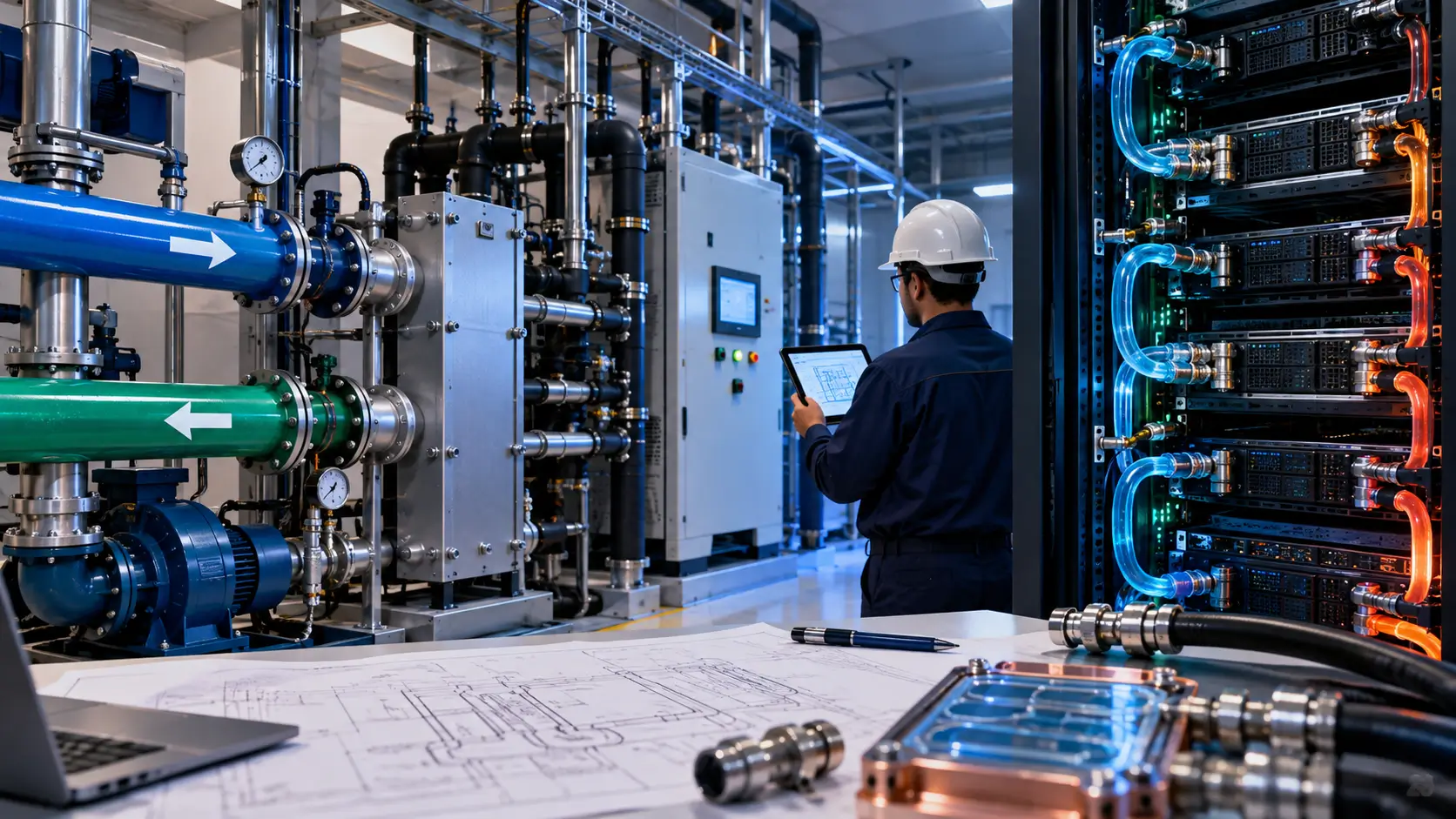
A liquid-cooled AI data center can reach an uncomfortable point even when every major component appears technically sound. The CDU may meet its published performance envelope. Cold plates may satisfy server requirements, while pumps provide their specified head. The external heat-rejection plant may also have enough nominal capacity. Yet those conditions do not prove that the assembled system will deliver the required coolant conditions at every rack. Temperature, differential pressure and flow must remain suitable when the compute workload reaches its intended operating state. The engineering challenge increasingly sits between components because each subsystem transfers operating conditions to the next part of the thermal chain. Hydraulic resistance can alter available flow as piping, valves, filters, manifolds, quick disconnects and cold plates add pressure losses. The real challenge is proving that the complete thermal system works under the conditions that production compute will create.

The Cooling Architecture Is Becoming One Connected System
Direct liquid cooling creates a thermal path that crosses several engineering boundaries before heat finally leaves the data center. A common liquid-to-liquid architecture separates the facility water system from the technology cooling system through a CDU. The CDU typically contains heat exchangers, pumps, sensors and control equipment. This separation allows the facility and technology sides to operate under different pressures and fluid requirements. Their thermal performance, however, remains physically connected. Heat moves from processors into cold plates and then into the technology-side coolant. Distribution hardware carries that heat toward the CDU before the facility loop moves it toward heat-rejection equipment. Each stage receives operating conditions from the previous stage and creates conditions for the next one. The design question is no longer whether individual devices meet specifications, but whether the complete operating chain supports the compute platform.
Facility Water Conditions Cannot Be Treated in Isolation
The facility water system creates an early opportunity for a reasonable assumption to spread through the entire design. ASHRAE guidance notes that designers should account for CDU approach temperature when establishing water conditions for IT equipment. A heat exchanger requires a temperature difference between its fluid circuits to transfer heat. Facility-side supply temperature therefore does not simply become technology-side supply temperature. Designers need to work backward from allowable IT coolant conditions through the CDU and into the facility-water operating envelope. Outdoor conditions can also influence sites where heat-rejection performance depends on the surrounding environment. In those cases, designers should verify performance across the environmental design conditions established for the facility. Condensation becomes another consideration when coolant temperatures approach the dew point of surrounding air. Temperature, pressure, filtration and flow must consequently form part of interface evaluation rather than treating temperature as the only design variable.
A CDU Rating Does Not Describe the Entire Hydraulic Network
A CDU’s cooling capacity represents performance under defined conditions. It does not guarantee that every connected rack will receive adequate coolant in every installation configuration. Reference CDU designs specify more than thermal capacity for this reason. They can include facility-side flow, technology-side flow, differential pressure, operating pressure and approach temperature. Pumps must overcome resistance throughout the connected hydraulic circuit rather than merely move coolant through the CDU. Pipes, fittings, valves, filters, hoses, manifolds and quick disconnects all contribute resistance. Cold plates add their own hydraulic characteristics to the circuit. Parallel rack branches introduce another variable because flow distribution depends on the resistance of individual paths. Therefore, hydraulic calculations need to extend from the cooling source to the relevant IT interfaces. A system becomes useful to the compute environment only when sufficient coolant reaches the equipment producing the heat.

Small Interfaces Can Carry System-Level Consequences
Some of the most consequential thermal interfaces are physically small compared with the infrastructure around them. Quick disconnects, rack manifolds, hoses and cold-plate connections sit close to the compute hardware. Their pressure drop, sealing behavior, material compatibility and service requirements can affect the wider technology cooling circuit. Cold plates, tubing, manifolds, quick disconnects and CDUs form parts of the same fluid path. Standard connection dimensions can improve mechanical interoperability, but mechanical fit does not establish complete hydraulic compatibility. Flow capacity still has to match the required operating range. Coolant chemistry also needs to remain compatible with wetted materials throughout the circuit. Filtration matters because contamination can affect narrow fluid passages and other cooling components. Moreover, maintenance can change the hydraulic configuration when technicians isolate or replace equipment. These interfaces deserve system-level attention before their effects appear during commissioning or production operation.
Redundancy Must Survive the Loss of Real Equipment
A redundancy diagram can look convincing without proving that cooling performance will survive an actual equipment failure. An N+1 pump arrangement provides spare pumping capability, but resilience depends on more than pump count. Electrical feeds, controls, isolation devices and common piping can influence what remains available after a failure. Reference architectures for high-density cooling use redundant pumps, power arrangements and CDU groups to support continued operation or maintenance. Rack-level isolation can also limit the effect of some cooling faults. These approaches highlight an important engineering distinction between component redundancy and system resilience. Two redundant devices may still depend on common upstream infrastructure. A shared control or distribution element can also influence several otherwise independent branches. Failure analysis should examine flow, pressure, temperature and controls after the assumed equipment loss. Thermal redundancy becomes meaningful when the surviving architecture can still provide the required operating conditions.
Controls Have Become Part of Thermal Capacity
Modern liquid cooling depends on information moving through the infrastructure almost as much as coolant moving through pipes. Sensors can report temperatures, differential pressure, flow rates and system pressure. These measurements help operators understand whether the thermal circuit remains inside its intended operating envelope. Monitoring architectures can track CDU supply temperature, return temperature, differential pressure, flow and system pressure as separate data points. Those values can help teams investigate whether an abnormal condition originates in load, pumping or distribution. Instrument location also matters. A measurement taken at the CDU does not necessarily describe conditions at a distant rack. Control sequences must coordinate pumps, valves and monitored conditions as thermal demand changes. However, telemetry becomes useful only when teams define acceptable ranges, alarms and operational responses. Reliable visibility gives operators stronger evidence that cooling capacity is actually reaching the compute hardware.
Commissioning Has to Prove More Than Equipment Startup
Equipment startup and integrated thermal validation answer different engineering questions. Startup can establish that a pump runs, a valve moves or a sensor reports a value. A CDU can also reach its expected operating state during an equipment-level test. Those observations do not prove that the complete cooling chain can support the intended IT load. Integrated commissioning examines how installed equipment behaves as a connected system. Engineers can test flow distribution, temperature stability, differential pressure, control interaction and alarm behavior under defined conditions. Failure scenarios deserve particular attention because normal operation can conceal dependencies. A pump transition or CDU outage can alter system pressure and flow distribution. Commissioning plans should connect tests to the performance assumptions established during design. System-level verification then becomes evidence of infrastructure readiness rather than a collection of equipment startup records.
The Test Boundary Should Reach the Rack
Testing only at the plant or CDU can leave the final part of the thermal path insufficiently characterized. Compute hardware receives coolant after it passes through distribution piping, branch connections, manifolds and rack interfaces. Those endpoints therefore matter during validation. Measurements at representative racks can show whether predicted hydraulic behavior matches installed conditions. Remote or hydraulically disadvantaged branches may experience different differential-pressure conditions. Distribution topology, hydraulic resistance, pump operation, balancing arrangements and valve states can all influence those conditions. Simultaneous operation matters because many active branches create different hydraulic conditions than a single branch under test. Instead, testing should represent the operating configurations that the facility expects to support. Rack-level temperature, pressure and flow measurements can then connect plant capability with conditions actually available to the compute equipment.
Procurement Can Freeze Assumptions Earlier Than Expected
Commercial consequences begin before a cooling system enters service because procurement turns engineering assumptions into purchased equipment. CDU capacity, heat-exchanger characteristics, pipe sizing and pump selection can become difficult to change once orders advance. Valve arrangements, manifold geometry and rack interfaces can create similar constraints. A project can therefore retain integration risk even when individual procurement packages meet their own technical requirements. Vendor boundaries can make this problem harder to see. The facility plant, CDU, distribution network and IT hardware may come from different suppliers. Each supplier can define the conditions required by its own equipment. Someone still needs to reconcile those requirements across the complete thermal chain. The reference post frames this as an integration risk that should be addressed before procurement and deployment commitments limit design flexibility. Clear interface requirements give teams a stronger basis for evaluating equipment selections and later substitutions.
Customer Capacity Depends on Usable Thermal Capacity
For an AI infrastructure customer, electrical capacity and floor space alone do not establish usable rack capacity. Cooling must remove the heat generated by a specific configuration while maintaining the coolant conditions required by the IT hardware. Thermal capability therefore forms part of the practical capacity envelope of a high-density deployment. A facility may have substantial aggregate heat-rejection capability while a local hydraulic constraint limits one distribution branch. Improving one part of the thermal chain may also fail to increase rack capacity when another interface remains constrained. Capacity planning needs alignment between IT load, rack distribution and CDU operation. Facility-water conditions and heat rejection must fit the same operating model. Customers can ask which conditions the provider has validated at the rack interface. They can also examine whether those conditions remain available during expected maintenance and failure states. Integrated testing provides evidence about installed behavior that component nameplates alone cannot provide.
Interface Ownership Is Becoming an Infrastructure Discipline
Liquid cooling creates an accountability question that individual equipment specifications cannot resolve. Facility engineers may own the primary water system, while mechanical contractors deliver distribution piping. A CDU supplier can define equipment limits, and server manufacturers can specify technology-side requirements. Operations teams eventually inherit the completed installation. Each party may satisfy its own scope while an integration gap remains between those scopes. Projects therefore need clearly documented conditions at the interfaces connecting each part of the thermal chain. Those conditions can cover temperature, flow, pressure, fluid characteristics, controls and expected failure behavior. Design reviews can then assess changes against shared operating requirements rather than isolated equipment specifications. Standardization around CDUs, cold plates and connection hardware provides useful building blocks, but it does not remove site-specific engineering. Piping topology, redundancy, controls and installed compute still determine how the complete system behaves.
Liquid Cooling Readiness Needs Evidence Before Capacity Goes Live
The engineering shift is subtle but important. Successful thermal design cannot rely only on selecting capable equipment and assuming compatible specifications will create a capable system. AI infrastructure places large thermal loads behind a connected chain of equipment and operating conditions. Facility water, heat exchangers, pumps, controls, distribution hardware, manifolds and cold plates all contribute to that chain. Design teams need to establish the acceptable operating envelope at each important interface. They also need to verify whether the installed system stays within those limits under relevant production states. Procurement decisions should preserve those conditions, while equipment substitutions deserve review when they change hydraulic or thermal behavior. Commissioning should test credible operating and failure conditions rather than only confirming that individual equipment starts. Operators then need telemetry that shows whether required conditions continue to reach the compute hardware. None of this means liquid cooling is inherently unreliable. It means system-level evidence becomes essential when cooling performance depends on multiple interconnected layers.
The central risk appears when every supplier can demonstrate a compliant component but the project cannot demonstrate compliant system behavior. That distinction matters because servers do not experience a CDU’s nameplate rating or a plant’s theoretical cooling capacity. They experience the temperature, flow and pressure available at their own cooling interfaces. A robust architecture connects those rack conditions to measurable requirements established during design. Procurement teams preserve the requirements when equipment selections change. Commissioning teams test them after installation, while operations teams monitor them throughout service. This approach also creates a clearer basis for investigating performance problems because teams can trace conditions across the thermal chain. Interface ownership becomes more important as rack power rises and a larger share of processor heat enters liquid circuits. The goal is not to make cooling architecture more complicated than necessary. It is to prove that the infrastructure can deliver the thermal conditions on which the promised compute capacity depends.











