Skip to content


A data center can maintain stable server temperatures, meet its operating requirements, and pass routine inspections while losing cooling efficiency through gaps that rarely attract sustained attention. The problem does not necessarily announce itself through an alarm, a failed component, or an obvious change in equipment behavior, because the air moving through an imperfectly sealed environment can still deliver enough cooling to keep the computing load operating within acceptable conditions. What changes is the amount of work required to maintain that stability, as cooling equipment compensates for unwanted mixing, airflow takes paths that designers never intended, and control systems gradually adapt to conditions that should not have become normal. These effects can remain distributed across an entire site, making them difficult to isolate when operators evaluate cooling performance through equipment readings rather than the behavior of the complete thermal environment.

The underlying issue is not simply whether a site has installed physical barriers around its hot or cold aisles, but whether those barriers continue to control airflow under real operating conditions. Cable routes, ceiling interfaces, pressure differences, equipment changes, and maintenance activity can create pathways through which air escapes its intended circuit, even when the original installation appears complete. An opening above a contained aisle can permit air to move between regions that the containment design intends to separate, with the direction and magnitude of that movement depending on the local pressure difference, opening geometry, available airflow paths, and operation of nearby cooling equipment. The resulting temperature pattern may look manageable at an individual sensor while concealing a larger redistribution of airflow across neighboring racks and cooling zones.
Installed Containment vs Effective Containment: Where the Gap Lives
Containment begins as a physical design decision, but its value depends on whether the completed installation establishes a reliable airflow boundary throughout the operating life of the site. Doors, roof panels, end-of-row barriers, blanking panels, and carefully arranged supply and return paths can reduce unwanted contact between hot exhaust air and cold supply air, yet their presence alone does not establish that the intended airflow separation works under actual operating conditions. The boundary must remain effective around the equipment, building interfaces, cable penetrations, and service routes that collectively shape the movement of air through the hall. A drawing may show a continuous enclosure while the installed condition contains narrow openings, poorly fitted panels, displaced seals, or unprotected transitions that create alternative routes between pressure zones.
Installed Barriers and the Airflow They Must Control
An opening above an aisle warrants inspection because it can connect spaces that the containment design intends to keep thermally separated, although its actual effect depends on the opening’s geometry, the pressure difference across it, and the resistance of surrounding airflow paths. Depending on the configuration, warm return air may move through this gap toward the cold side, or conditioned air may escape into a region where it does not contribute directly to server inlet cooling. Neither pathway operates independently of the surrounding pressure field, so the direction and strength of leakage can change as fans modulate, cooling units cycle, rack populations change, and neighboring zones develop different airflow requirements. When leakage changes the intended airflow path, the installed enclosure may no longer deliver the separation assumed in the design, and engineers must verify the resulting temperature and pressure patterns under representative operating conditions.

The operational significance becomes clearer when the site treats containment as part of the cooling system rather than as a collection of construction accessories. Cooling equipment produces and circulates air, but the enclosure determines where that air travels, how much heat it collects, and whether it returns through the intended path. When the boundary leaks, a cooling unit may continue delivering its specified airflow while the servers receive a less useful distribution of that airflow than the design anticipated. The mechanical system can respond to this mismatch through greater circulation, lower supply temperatures, or revised control behavior, although the exact response depends on the installed architecture and operating conditions. Those adjustments can obscure the original defect because they restore acceptable readings without restoring the intended flow pattern.
The Roof-Line Blind Spot and Its Operational Consequences
The roof line can present an inspection challenge because cable trays, structural supports, overhead services, and ceiling transitions can obstruct access to containment interfaces, making it important to include these areas in airflow inspections. Above the racks, however, cable trays, containment roofs, lighting, structural supports, fire-protection interfaces, and overhead services can interrupt the continuity of the enclosure or make its condition difficult to assess. An opening may arise during installation, emerge after cable additions, or develop when maintenance teams remove and reinstall panels without restoring the original seal. The resulting path can remain unnoticed because the airflow crossing it does not necessarily produce an immediate equipment alarm, especially when neighboring cooling units have sufficient capacity to compensate.
After commissioning, cable additions, equipment replacements, and maintenance work can alter the geometry of the containment boundary, so operators should inspect affected interfaces and verify that the intended airflow separation remains effective. Additional network cabling, replacement racks, revised service access, temporary equipment moves, and changes to overhead routing can alter the geometry of a previously controlled space. Each intervention may appear reasonable when considered on its own, but the accumulated effect can create a connected set of leakage paths that changes the relationship between supply air, exhaust air, and return air. A gap above one aisle may also interact with openings in neighboring containment sections, suspended ceilings, or shared return spaces, allowing airflow to travel along routes that do not match the original design assumptions.
The Two-Degree Drift That Reshapes Inlet Conditions
A server inlet temperature does not tell the complete story of how effectively a cooling system delivers conditioned air to the equipment that needs it. The reading captures conditions at a particular location and moment, while the surrounding airflow determines whether that condition remains representative of the rack, the aisle, and the wider hall during changing workloads. When warm exhaust air mixes with supply air before the latter reaches server inlets, the resulting inlet-temperature profile can change, but whether the change triggers an alarm depends on sensor placement, alarm thresholds, and the site’s monitoring configuration. The equipment may continue operating within its permitted thermal envelope, yet the cooling system now manages a different set of conditions from those anticipated during design. A temperature change of a few degrees can also influence the response of variable-speed fans, cooling-unit controls, and supply-temperature regulation, depending on their configuration and control logic.
How Small Temperature Changes Alter the Cooling Response
The phrase two-degree drift describes a potential operating condition rather than a universal performance penalty, because the effect of a temperature change depends on where the change occurs and how the cooling system responds. A rise at one inlet sensor does not establish that every rack experiences the same increase, and a two-degree change in supply temperature does not necessarily produce the same energy impact as a two-degree increase caused by recirculated exhaust air. The first situation may reflect a deliberate control adjustment, whereas the second may indicate that the enclosure permits warmer air to enter a path intended for conditioned supply air. Both conditions deserve attention, but they require different diagnoses and may produce different consequences for fan power, cooling capacity, and equipment operating margins. Reliable analysis therefore begins by identifying the temperature reference, the sensor location, the direction of airflow, and the operating state associated with the reading.
A persistent inlet-temperature shift can nevertheless change the way a site uses its available cooling capacity, particularly when control systems respond to the warmest monitored locations rather than the average condition across a hall. An operator may lower the supply-air temperature to protect a rack experiencing recirculation, even though other racks already receive sufficient cooling and would not benefit from the adjustment. Cooling units may also increase airflow when their sensors detect warmer return conditions or when control sequences attempt to maintain a target temperature across an uneven load. These responses can preserve the required operating environment, but they may increase electricity consumption or create additional airflow imbalances elsewhere in the system. The resulting behavior depends on sensor placement, control deadbands, cooling-unit characteristics, and the relationship between local equipment demand and central plant operation.
Why Design Conditions Become Harder to Maintain
Design conditions describe an intended operating envelope, but actual airflow depends on the resistance and pressure relationships of the installed system. Supply air follows the available paths through floor openings, ducts, cooling units, containment boundaries, and equipment rather than following the designer’s preferred route simply because the drawings specify it. When a gap develops above an aisle, the opening can change the local pressure balance and allow air to move between regions that the original arrangement intended to separate. That movement can alter the temperature and volume of air reaching nearby racks, while the response of adjacent cooling equipment may shift the airflow distribution again. The site can consequently experience a more complicated thermal pattern than a simple comparison between a design temperature and an operating temperature suggests.
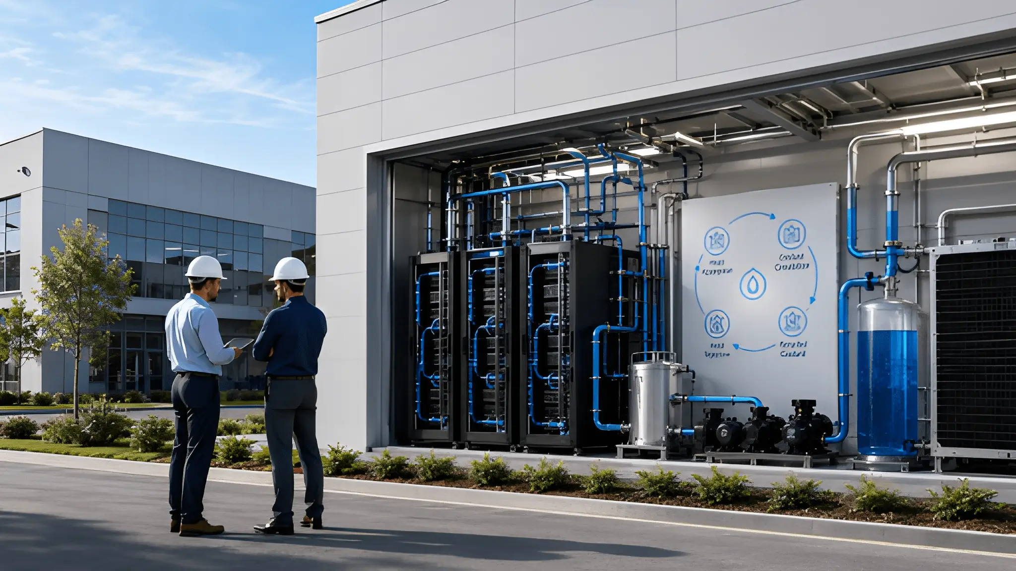
Water-based cooling introduces another layer to this analysis because the temperature and airflow conditions around the servers interact with the wider process used to remove heat from the site. A chilled-water system may supply cooling coils that condition the air, while a liquid-cooling arrangement may transfer heat from selected components into a separate fluid circuit before rejecting it elsewhere. In either case, the installed system must accommodate the actual thermal load, and unwanted air mixing can complicate the operation of equipment that still relies on air-side cooling. A lower supply-air temperature can also affect the wider cooling strategy, depending on coil performance, control settings, ambient conditions, and the configuration of the heat-rejection equipment. The relationship does not support a universal claim that every leakage defect increases water consumption or that every two-degree change forces a particular increase in plant energy.
From Aisle-Level Anomaly to Hall-Wide Behavior
A localized opening above an aisle can influence a larger area because air movement responds to connected pressure zones rather than to the visual boundaries that separate equipment rows. When supply air, exhaust air, and return spaces communicate through unintended openings, the resulting paths can carry heat beyond the immediate location of the defect. The direction of movement depends on the pressure relationships across the opening, the resistance of alternative routes, and the operation of nearby fans and cooling equipment. Warm air that escapes its intended return path may enter a neighboring region, while conditioned air may bypass the rack and mix with warmer air elsewhere in the hall. Where connected pressure zones and airflow paths permit propagation, leakage can alter thermal conditions beyond the immediate opening, but the extent of any effect on neighboring racks must be established through site-specific airflow and temperature measurements or a validated model.
The Airflow Path Does Not Stop at the Leak
Cross-aisle effects warrant investigation when containment sections share overhead spaces, return-air plenums, or other connected regions, because those connections can permit airflow between zones depending on the local pressure distribution and resistance of the available paths. Under these conditions, a local opening can form one segment of a longer path that allows air to move between aisles, rather than simply leaking into an isolated space. The resulting pattern may redistribute heat unevenly, producing warmer regions near some racks and excess cooling in others as the control system attempts to preserve acceptable conditions throughout the hall. An operator who examines only the original aisle may identify the physical gap but miss the broader consequences created by adjacent pressure zones and connected return paths.
The propagation mechanism does not imply that every opening will produce hall-wide recirculation, because some defects remain confined by the surrounding geometry or by favorable pressure conditions. A gap may carry little air under one operating state, while a change in fan output or return-air resistance can make it a more important pathway under another. Engineers need to establish the direction, persistence, and approximate scale of the airflow before treating a visible opening as the cause of a broad temperature anomaly. Smoke visualization, suitable airflow measurements, differential-pressure readings, thermal mapping, and inspection of the installed enclosure can help build that picture when teams apply them safely and interpret them in context. Sensor data becomes more valuable when operators compare readings across neighboring aisles and operating periods, rather than treating each temperature measurement as an independent observation.
Uneven Thermal Distribution and the Cost of Compensation
Once unwanted airflow moves beyond its point of entry, the cooling system must manage a thermal environment in which temperature, airflow demand, and equipment loading may no longer align neatly. A heavily loaded rack can require substantial airflow while a neighboring rack with a lighter workload receives more conditioned air than it needs, especially when the distribution system cannot independently regulate every local condition. Leakage can intensify that imbalance by introducing warm air into a supply path or allowing conditioned air to escape before it reaches the equipment. Depending on sensor placement and control logic, the cooling system may respond to a warm monitored location by changing airflow or supply conditions across a wider zone, potentially affecting areas beyond the original defect. This response can protect equipment, but it can also increase cooling effort for racks that never experienced a meaningful thermal problem.
This hall-wide perspective becomes more important when a site plans to introduce higher-density computing or alter the balance between air cooling and liquid cooling. A configuration that operates acceptably under one rack arrangement may behave differently after equipment changes redistribute airflow demand or change the heat released into the surrounding environment. Liquid-cooled equipment can reduce the amount of heat that enters the room air, depending on the proportion of the load captured by the liquid circuit, but it does not remove the need to manage residual heat and maintain suitable conditions for air-cooled components. A site that expands liquid cooling without correcting existing containment defects may therefore preserve some of its previous airflow inefficiencies while adding new requirements for pumps, fluid distribution, and heat rejection.
The Compounding Curve: Modeling MWh and Carbon at Portfolio Scale
A credible estimate of the energy cost associated with leakage begins with a measured baseline rather than a generic assumption about how much electricity a temperature increase consumes. The analysis must separate the electricity used by computing equipment from the electricity used by cooling equipment, because a containment defect does not automatically increase server power simply because the inlet temperature changes. Any effect on computing power depends on the equipment, workload, thermal response, and operating controls, while the more direct pathway usually involves the cooling system’s response to altered airflow and heat distribution. Engineers should establish how the site performs under representative conditions before corrective work, using available measurements of cooling-unit power, fan operation, supply temperatures, return temperatures, and the relevant IT load.
Establishing a Defensible Energy Baseline
The next step is to identify the additional cooling electricity that the site can reasonably attribute to the leakage condition. The measured or modeled increment may include changes in fan electricity, cooling-unit operation, chiller demand, or other relevant equipment, but each contribution must be established from site measurements or a validated model rather than attributed to leakage by assumption. The contribution from each component depends on the installed system, so the analysis should avoid applying a single percentage increase across every cooling technology or assuming that a temperature deviation produces a uniform response. A site with variable-speed fans may respond differently from one with fixed-speed equipment, while a plant with substantial control flexibility may manage the same thermal disturbance differently from a system that operates within tighter constraints.
Once the additional electrical demand has been established, operators can calculate the associated energy over a chosen reporting period and compare it with the site’s broader operating profile. The basic relationship is straightforward: incremental energy equals the additional electrical demand attributable to leakage multiplied by the time that demand persists, provided both quantities use consistent units and the demand estimate reflects the actual operating interval. When the additional demand changes with workload, weather, or equipment state, the calculation should use time-resolved measurements or separate operating scenarios rather than assume that a single reading remains constant throughout the year. A portfolio model can then combine comparable site-level estimates while preserving the differences between cooling architectures, climate conditions, load profiles, and measurement quality.
Turning Persistent Cooling Loss Into Carbon Exposure
Carbon accounting follows the energy analysis, but it introduces an additional variable that prevents operators from using one universal emissions factor for every site. The carbon associated with incremental electricity depends on the relevant electricity supply and the accounting method used, including whether the analysis applies a location-based grid factor or another documented factor appropriate to the reporting purpose. A site drawing electricity from a grid with a relatively carbon-intensive generation mix may associate a different emissions impact with the same additional electricity consumption than a site operating under different grid conditions. Contractual renewable-energy arrangements can also affect reported emissions under particular accounting methods, but they do not necessarily change the physical electricity consumed by cooling equipment or the carbon intensity of every hour of grid supply.
The time dimension matters because a leakage condition can persist through multiple operating cycles, seasonal changes, maintenance windows, and equipment upgrades without appearing as a separate item in energy reports. If measurements establish that a leakage condition causes additional cooling demand and that demand persists over an extended operating period, the associated electricity consumption can accumulate over time, with the total depending on the magnitude and duration of the measured increment. The calculation must still distinguish between continuous leakage and intermittent effects, since a defect that becomes influential only under certain pressure conditions will not produce the same energy impact as one that affects the system throughout its operating schedule. Analysts should also account for repairs, equipment changes, and shifts in workload rather than extending an early measurement across the entire historical period without evidence.
Operational Normalization: When Workarounds Become Standard Practice
A cooling workaround often begins as a sensible response to an immediate operating condition, particularly when an engineer needs to protect equipment while a permanent repair awaits access, approval, or a suitable maintenance window. Lowering the supply-air temperature can help address warm inlet conditions, while increasing fan output may improve air delivery to a rack that receives insufficient flow. These adjustments can restore acceptable conditions without requiring an immediate change to the physical containment boundary, which makes them attractive during busy operating periods. If an operational adjustment remains in place after the original problem has been resolved or reassessed, the site may continue using a control setting that no longer reflects its actual thermal requirements, making periodic review important for identifying avoidable cooling demand.
How Setpoint Adjustments Conceal the Original Defect
Setpoint changes can also obscure the relationship between the original leakage path and the energy used to maintain stable temperatures. When an operator lowers the supply-air target, the cooling plant may need to produce colder water or operate under different conditions, depending on the system configuration and the ambient environment. A change in fan speed can increase the electricity required for air circulation, while a broader control adjustment may alter how neighboring cooling units share the load. These effects do not occur identically in every installation, and a lower setpoint does not automatically produce a particular increase in plant consumption. Nevertheless, each adjustment can introduce a measurable operating cost that deserves investigation when it responds to a persistent containment defect.
The challenge is not to eliminate every operational adjustment, because workloads, ambient conditions, equipment populations, and maintenance requirements naturally change over time. Instead, teams need to separate adjustments that respond to legitimate changes in demand from those that compensate for avoidable defects in the installed airflow system. A useful control record should document the reason for a setpoint change, the condition it addresses, the expected duration, and the evidence required to return the system to its intended operating range. When an operational adjustment remains in place for an extended period, the maintenance record should document its original purpose, the condition it addresses, and the evidence needed to determine whether it remains necessary. Engineers can then assess whether the change improves the intended thermal outcome, increases energy consumption elsewhere, or creates new imbalances that require further investigation.
Fan Bias, Control Drift, and the Cost of Familiarity
Fan bias can develop when teams repeatedly increase airflow in response to uneven inlet conditions, even though the underlying cause lies in the distribution system rather than a genuine shortage of cooling capacity. Higher fan output may help a rack receive the air it needs, but the additional circulation can also change pressure relationships and influence how air moves through neighboring containment sections. The resulting response can make a leakage defect harder to diagnose if the adjusted fan output improves local temperature readings without correcting the underlying airflow path, a possibility that engineers should test through physical inspection and airflow measurements. If other cooling units respond to the changed pressure or return-air conditions, the site may develop a pattern in which several components compensate for one physical defect. Operators can then struggle to identify the original cause because the observed symptoms appear across multiple units and locations.
The connection to water-cooled infrastructure becomes particularly relevant when operators use control adjustments to compensate for an air-side problem while considering a larger cooling upgrade. A site may attribute persistent cooling demand to limitations in its existing technology and begin evaluating chilled-water improvements or direct liquid cooling, even though part of the observed demand arises from poor airflow management. A different cooling architecture may still offer sound technical benefits, particularly where computing density or equipment requirements justify it, but the business case should separate those benefits from savings that a containment repair could deliver independently. Otherwise, the site risks comparing the full cost of a technology change against an operating baseline that includes avoidable inefficiency. A properly documented baseline allows engineers to evaluate the existing system under improved containment conditions before estimating the incremental value of new cooling equipment.
Sealing Integrity as a Design Discipline, Not a Punch List Item
Containment performance depends on details that extend beyond the equipment layout and the initial installation drawings. Cable trays, overhead service routes, structural transitions, and interfaces with return-air spaces can interrupt the intended boundary unless the design accommodates them as part of the airflow system. A panel may fit correctly when installed but leave an unintended opening after cable additions, equipment replacement, or changes to service access. These conditions make sealing integrity an ongoing engineering responsibility rather than a task that ends when the construction team closes its punch list. Design reviews should identify the interfaces most likely to change during operation, establish suitable sealing methods, and preserve access for inspection without encouraging technicians to leave temporary openings behind. The resulting approach treats the enclosure as an active part of the cooling architecture and accounts for the work required to maintain its performance after the site enters service.
Designing for Cable Routes, Plenums, and Field Conditions
Cable penetrations deserve particular care because their geometry changes with the volume, arrangement, and routing of installed services. A design that leaves generous open space around future cable additions may simplify installation, but it can also create a persistent path between regions that should remain thermally separated. Conversely, an overly rigid sealing arrangement may complicate legitimate maintenance or make later changes difficult to complete without damaging the boundary. Engineers should select sealing methods suited to the specific penetration, the expected maintenance requirements, and applicable fire-safety and building-code obligations, using approved materials and installation methods rather than improvised solutions. The solution must suit the location and purpose of the penetration rather than rely on an improvised material that may not perform safely or reliably under operating conditions.
Plenum interfaces create a related challenge because the pressure and airflow conditions above or around the contained aisle can change when the building’s return-air arrangement, ceiling geometry, or cooling configuration changes. An opening at an interface may have little influence under one operating state but become a more important leakage path when fan output, system resistance, or the distribution of cooling demand changes. A durable design should document the intended pressure boundary, the treatment of interfaces, and the locations requiring inspection, with verification criteria appropriate to the installed configuration and the operating conditions of the site. Field teams also need clear acceptance criteria so they can identify incomplete sealing without relying on subjective judgments about whether an opening looks large enough to matter. The inspection should verify the actual installation against the design while accounting for legitimate service access and any system-specific safety requirements.
Making Containment Performance Part of Routine Operations
A sealing program becomes more reliable when operators incorporate containment checks into the maintenance activities that already affect airflow and thermal conditions. Rack replacements, cable installations, cooling-unit service, and changes to overhead infrastructure can all alter the physical boundary, making these events useful triggers for targeted inspection. The maintenance record should identify the affected location, the reason for opening the boundary, the method used to restore it, and the verification completed before the work closes. This record can help engineers investigate later thermal anomalies by linking observed conditions with documented changes to the installed environment, although identifying a causal relationship still requires supporting technical evidence. It also prevents responsibility from becoming fragmented between construction, cooling operations, cabling, and maintenance teams, each of which may control only part of the final arrangement. A consistent process makes containment integrity an observable operating condition rather than an assumption inherited from the original installation.
Verification should combine physical inspection with evidence that the repaired boundary changes the behavior that prompted the work. Depending on the site, this may involve comparing inlet-temperature patterns, checking differential pressure, observing airflow direction, reviewing fan operation, or examining cooling electricity under comparable conditions. A repair that closes a visible gap but produces no meaningful change in the suspected airflow path may require further investigation, because another opening or a different pressure relationship could continue to drive the anomaly. Conversely, a measured improvement in airflow distribution may confirm that the repair addressed the thermal mechanism even when the energy effect remains too small to isolate confidently from normal operating variation. Engineers should document both the immediate physical result and the subsequent operating evidence, while retaining uncertainty where measurements cannot establish a direct causal relationship.
Closing the Gap That Never Registered as a Gap
The cost of low-grade leakage often remains hidden because the operating system can compensate for a defect without allowing it to develop into an obvious thermal incident. A site may maintain acceptable inlet conditions while its fans, cooling units, and control sequences respond to airflow that no longer follows the intended route. The energy consequences depend on the leakage path, the operating state, the cooling architecture, and the extent to which the system must compensate to preserve its required conditions. That variability makes measurement essential, because neither a visible opening nor a small temperature deviation establishes a universal energy penalty. A disciplined assessment identifies the physical defect, establishes a credible baseline, verifies the corrective action, and measures the resulting change without confusing modeled potential with demonstrated savings. This approach gives operators a defensible basis for determining whether containment repairs can recover performance before they commit resources to larger cooling modifications.
Recovering Performance Before Replacing the Cooling System
The relationship between containment and water-cooled infrastructure deserves particular attention as operators evaluate different methods of managing growing thermal loads. Chilled-water systems and direct liquid cooling can address specific heat-transfer requirements, but their performance depends on the configuration of the complete system and the conditions under which it operates. Air-side leakage can remain relevant wherever server components, supporting equipment, or residual heat loads still depend on controlled airflow. Correcting that leakage does not replace the engineering case for liquid cooling, nor does it establish that an existing air-cooled arrangement will always provide the best outcome. It creates a more reliable baseline from which engineers can compare cooling options, assess operating costs, and understand how much additional infrastructure a site genuinely needs. The decision becomes more useful when it separates the benefits of a technology change from the avoidable losses that better containment can address within the existing installation.
Portfolio analysis extends this discipline from individual repairs to a consistent method for evaluating operating performance across multiple sites. Engineers can document the location and character of leakage, the observed thermal response, the associated control adjustments, the measured electricity demand, and the confidence attached to each estimate. A common methodology allows operators to compare results while retaining the differences between local climates, cooling architectures, workload profiles, and operating histories. Carbon estimates can then follow the documented energy calculations, using appropriate electricity emissions factors and a clearly stated accounting method. Where direct measurements cannot isolate the effect of leakage, transparent scenarios can establish the range of potential outcomes without presenting uncertain estimates as verified savings. This combination of physical inspection, operational evidence, and disciplined accounting turns containment integrity into a measurable component of long-term cooling performance.
Making Invisible Leakage Visible in the Operating Record
The lasting improvement comes when sealing integrity becomes part of how a site records changes, investigates anomalies, and verifies the performance of its cooling system. Maintenance teams need a clear process for restoring containment after service work, while engineering teams need enough information to determine whether a temperature shift reflects leakage, workload changes, control drift, or another cause. Operators should preserve the reasoning behind setpoint changes and fan adjustments so that later reviews can identify workarounds that no longer serve a legitimate purpose. Physical inspections should examine overhead interfaces, cable penetrations, and return-air boundaries alongside the temperature and pressure patterns that reveal how the system behaves. Corrective work should then include a suitable verification step, with measurements interpreted against the conditions that existed before the repair. These practices help operators identify and document containment defects that might otherwise remain unresolved while the site continues to meet its immediate thermal requirements.
Low-grade leakage becomes a high-grade operational concern when teams allow a small airflow defect to persist without measuring the work required to compensate for it. The path from an overhead opening to portfolio-level energy and carbon exposure is not automatic, but engineers can investigate it through a consistent combination of airflow diagnosis, electrical measurement, and operating-history analysis. That evidence helps establish which sites have recoverable inefficiencies and which require a different intervention to address their underlying thermal constraints. It also creates a stronger foundation for decisions about water-based cooling, because the existing system’s performance becomes easier to evaluate once avoidable airflow problems no longer distort the baseline. The objective is not to promise a fixed reduction in energy consumption from every repair, but to identify and correct losses that the evidence shows the site can avoid.