Skip to content


Arctic air offers data center operators an extraordinary thermal resource, but cold weather alone cannot guarantee an efficient cooling system. A high-density computing hall can still reject substantial heat from power conversion, distribution losses, processors, and supporting electrical equipment before the outdoor environment can help remove it. The opportunity lies in redesigning how electricity reaches the rack and how heat leaves the silicon, rather than treating power delivery and cooling as separate engineering problems. Direct current distribution can reduce conversion stages and their associated losses, while a carefully engineered liquid loop can transfer the remaining heat toward the outdoor environment. When those systems work together, a site can reduce the amount of heat it generates internally and make more of its cooling demand compatible with ambient conditions.

The Heat You Never Have to Cool in the First Place
Every watt that reaches a processor does useful computational work or eventually becomes heat, but the electrical path determines how much additional heat the facility must manage. Conventional power architectures often convert electricity between alternating current and direct current at several stages, with each conversion releasing losses through semiconductor devices, magnetic components, and associated electrical equipment. A direct-current architecture can reduce unnecessary conversion stages by delivering power in a form that compatible computing equipment can use with fewer intermediate transformations. That change does not eliminate the heat generated by processors, memory, or unavoidable power electronics, but it reduces the supporting electrical losses that add to the facility’s thermal burden. For a high-density computing hall, removing those losses can reduce both the electricity required to deliver a given workload and the heat that cooling equipment must remove.
A meaningful chiller-free design therefore starts with a power-loss inventory rather than a cooling-capacity target. Engineers need to account for conversion efficiency across the incoming supply, backup power equipment, distribution stages, rack-level conversion, and the final voltage regulation that processors require. A direct-current backbone can simplify this route when the selected equipment accepts its output voltage efficiently, but the remaining converters still produce heat, and their location determines how much of that heat enters the computing zone. Moving suitable conversion equipment into a separately cooled electrical area can prevent some conversion losses from adding directly to the computing hall’s cooling burden, although the facility must still account for and manage that heat elsewhere. This approach also changes the sizing exercise because engineers can calculate the residual thermal load after removing avoidable conversion stages instead of automatically carrying forward assumptions from a conventional architecture.
When the Busbar Stops Becoming a Heater Inside the Rack
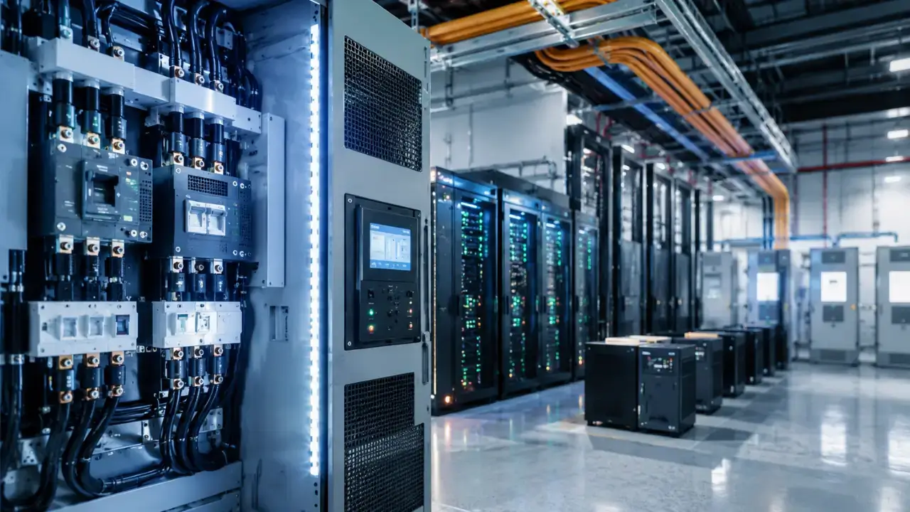
A rack-level power architecture can lose some of its efficiency advantage if its conductors generate unnecessary heat or obstruct the movement of air around power electronics. Solid, flat busbars offer a different packaging approach from bundles of flexible cables because their geometry can provide a compact, predictable distribution path with fewer overlapping conductors. Their broad exposed surfaces can support convective heat transfer when airflow, conductor orientation, and surrounding clearances favor heat removal, although the actual thermal performance depends on the complete installation. Flexible cables remain useful where equipment needs movement, modular connections, or adaptable routing, and their thermal performance relative to busbars depends on conductor resistance, cross-section, insulation, connection quality, and the surrounding airflow. The engineering question concerns conductor resistance, current density, connection quality, physical arrangement, and the airflow available to remove the resulting heat.

Busbar design becomes particularly important when a rack carries sustained high current, because resistive heating increases with the square of current for a given resistance. A conductor with resistance R dissipates power according to P=I2R, which means that small electrical inefficiencies can become consequential as current rises. Flat conductors can offer a useful combination of cross-sectional area and exposed surface, but their actual temperature depends on material, dimensions, joint resistance, insulation, mounting, airflow, and the electrical load. Engineers must also assess contact resistance at bolted or plated interfaces because a poorly executed joint can become a concentrated heat source even when the main busbar runs cool. Moreover, a clean busbar layout can make inspection and thermal monitoring more straightforward, allowing maintenance teams to identify abnormal temperature rises before they threaten availability.
Coupling Power Delivery Directly to Arctic Ambient
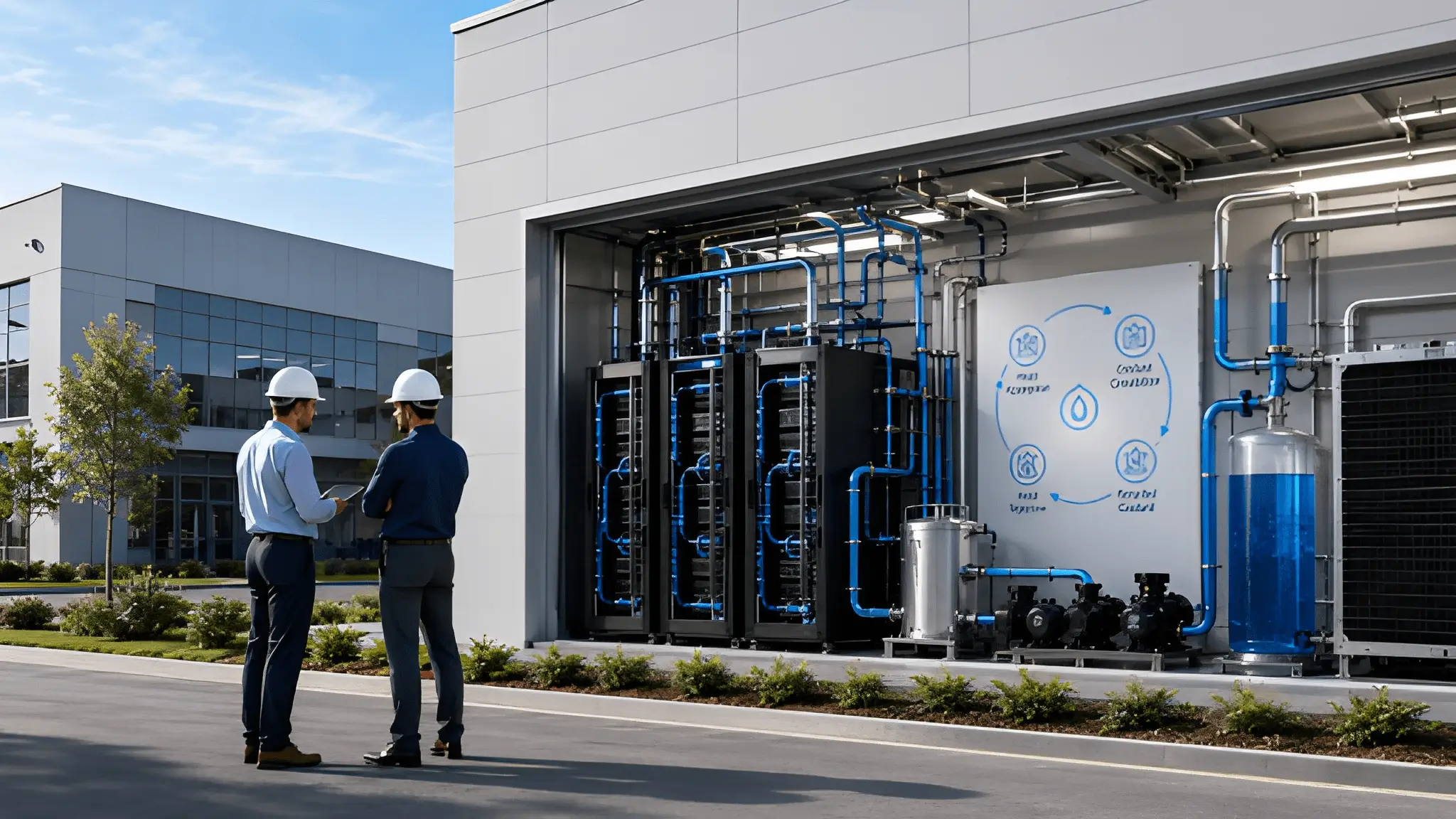
The strongest thermal advantage emerges when the electrical architecture and the coolant circuit form a coordinated route from power delivery to outdoor heat rejection. A direct-current backbone can supply compatible rack equipment through fewer conversion stages, while direct-to-chip cold plates capture processor heat close to its source and a suitably designed coolant circuit transfers that heat toward the outdoor environment. A suitably configured microchannel coolant distribution unit (mCDU) can circulate liquid through the cooling circuit and manage the flow, pressure, and heat exchange required by the rack design, depending on its specific capabilities and the overall system arrangement. The liquid absorbs heat at the chips and carries it toward a heat exchanger, where a facility loop can transfer that energy to an outdoor heat-rejection system sized to meet the required thermal load under the intended operating conditions.
The Arctic environment also introduces operating considerations that a temperature-only calculation can miss. Outdoor heat exchangers must manage snow accumulation, ice formation, wind exposure, seasonal changes, and maintenance access without creating unacceptable pressure drops or reducing heat-transfer performance. Liquid circuits need suitable freeze protection, material compatibility, leak detection, and controls that maintain stable operation during startup, shutdown, and rapid weather changes. Engineers must evaluate the difference between outdoor dry-bulb temperature and the coolant temperature required by the rack, because that approach temperature determines whether the heat exchanger can reject the load without refrigeration. A robust design also separates the outdoor environment from sensitive computing equipment, using controlled fluid circuits rather than exposing servers to uncontrolled ambient air.
Why Chiller-Free Is a System State, Not a Weather Condition
A chiller-free facility is not simply a building that operates during cold weather; it is a system that can maintain every critical temperature without mechanical refrigeration under its defined operating conditions. The power path must limit avoidable conversion losses, the rack backplane must distribute electricity without excessive resistive heating, and the coolant loop must carry processor heat at temperatures that the outdoor system can reject. Each component influences the operating margin available to the others, so optimizing one subsystem in isolation can create a constraint elsewhere. A high-temperature coolant loop cannot eliminate mechanical refrigeration if power electronics, networking equipment, or other components require temperatures that the available ambient heat-rejection system cannot maintain. Likewise, efficient direct-current distribution cannot compensate for a heat exchanger that lacks capacity during peak computing demand or unfavorable outdoor conditions.
Engineers must test this operating state against a complete range of conditions rather than a favorable winter design point. The analysis should include peak rack load, partial-load operation, pump failures, heat-exchanger fouling, coolant-flow restrictions, and periods when outdoor temperatures exceed the conditions under which ambient heat rejection alone can maintain equipment temperature limits. Controls must also prevent unnecessary chiller operation when ambient heat rejection remains adequate, while starting backup mechanical cooling when the system approaches a defined thermal limit. Ultimately, the target should be a documented operating envelope that identifies when the facility can run without chillers, what electrical and thermal conditions support that mode, and which contingencies require additional cooling capacity. This approach turns chiller-free operation into a verifiable engineering outcome rather than a marketing description based on local climate.
Chiller-Free Is Built in the Power Architecture, Not the Climate
Arctic locations can offer long periods of favorable heat-rejection conditions, but their climate alone does not determine the energy overhead of a high-density computing facility. The electrical distribution system influences how much heat the facility creates before computation begins, while the rack design determines how efficiently the remaining losses escape the power-delivery hardware. Direct-current distribution can reduce conversion stages, solid busbars can limit conductor losses when properly engineered, and direct-to-chip liquid cooling can capture processor heat before it spreads into the surrounding air. A compatible outdoor heat-rejection system can then use the available ambient temperature to remove that heat without operating a mechanical chiller. At rack densities above 100 kW, however, the design must verify electrical protection, coolant flow, heat-exchanger capacity, and equipment temperature limits under realistic operating conditions before claiming chiller-free performance.
The practical opportunity is to make the power architecture, rack distribution, and thermal circuit work as one continuous engineering system. Operators evaluating a new site should compare conversion losses, conductor temperatures, coolant supply requirements, auxiliary electricity use, and annual chiller operating hours before committing to a particular configuration. They should also calculate the energy overhead of pumps, fans, controls, and backup cooling instead of treating chiller elimination as equivalent to eliminating all cooling electricity. A properly designed facility may achieve extended chiller-free operation, although the achievable duration and energy savings depend on its workload, hardware requirements, ambient conditions, heat-rejection capacity, auxiliary electricity use, and redundancy strategy. Arctic conditions provide the thermal opportunity, but electrical and mechanical design determine how much of that opportunity becomes usable capacity and lower operating overhead. Chiller-free performance is ultimately engineered into the power path, not delivered by the climate alone.