
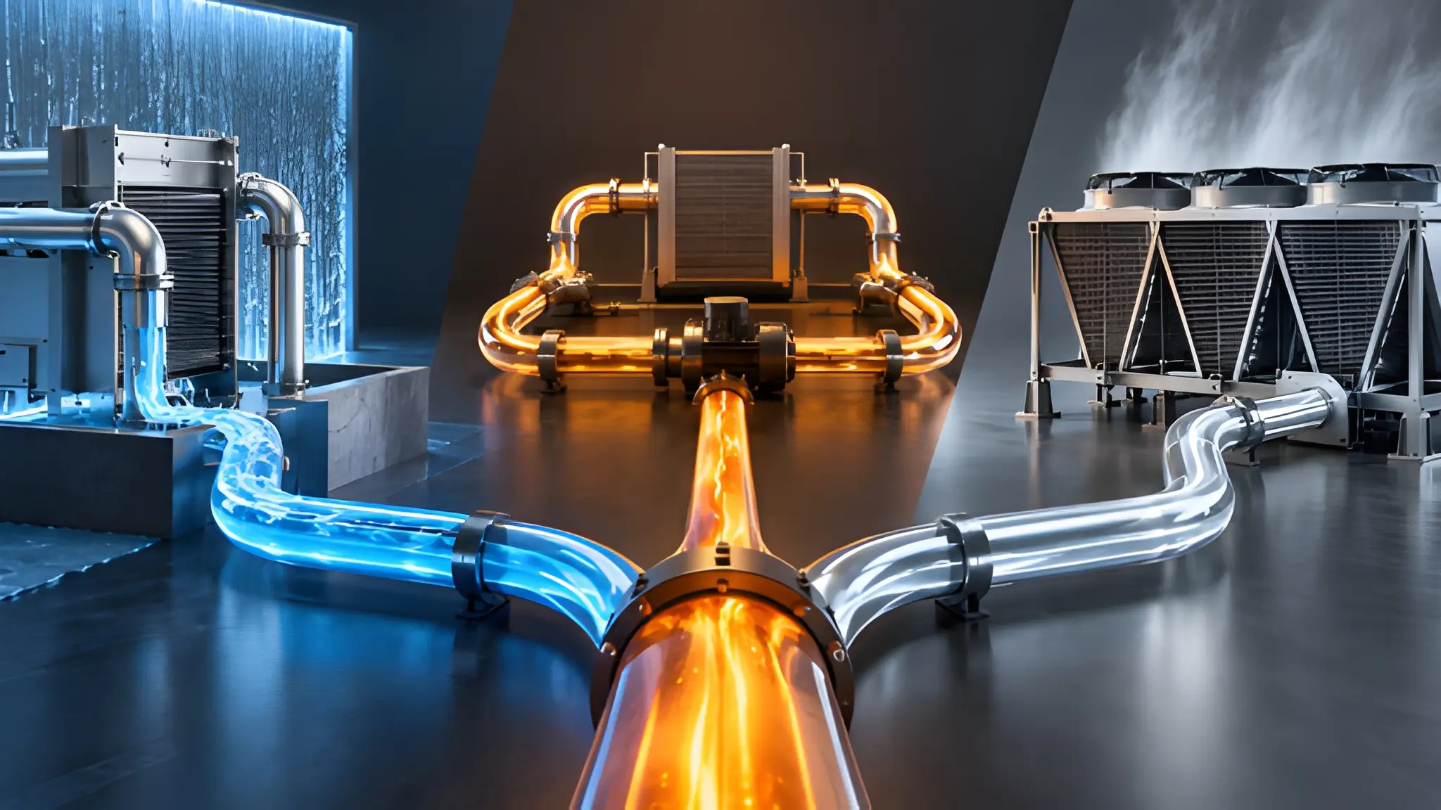
Rack density creates a thermal obligation that the rest of the cooling system must continuously satisfy, and the limiting factor often appears after heat leaves the chip rather than at the cold plate itself. A rack can accept higher compute power only when its captured heat can move through the secondary circuit and ultimately reach an outdoor rejection surface without exceeding temperature, flow, or pressure limits. That makes the rejection path part of the density calculation from the beginning, rather than a downstream utility selected after the rack and CDU have already been fixed. A cold plate may remove heat effectively at the device level while the broader system still struggles to discharge that heat at the required rate. The resulting constraint can force lower inlet temperatures, higher flow, larger heat exchangers, greater pumping power, or supplemental refrigeration.

The critical design variable is not simply how many kilowatts a cooler can nominally reject, but the temperature at which it can reject those kilowatts under the site’s actual outdoor conditions. A rejection device operating against a small temperature difference must move substantially more air, water, or refrigerant to maintain the same thermal output, which can increase equipment size and auxiliary energy consumption. Higher secondary-loop temperatures create a wider thermal margin against outdoor air and can make non-refrigerated rejection practical across more operating conditions. The available margin must include the CDU heat exchanger, pumps, manifolds, quick disconnects, tubing, and rack-level heat exchangers rather than treating the outdoor unit as an isolated component. A design that looks adequate at nominal load can lose useful density when outdoor temperature, flow imbalance, or fouling reduces its effective rejection capacity.
The Middle Layer That Locks Your Choice: Rack vs Floor CDU Behavior
CDU placement determines how the secondary circuit behaves before heat ever reaches the outdoor rejection equipment, making rack-level and floor-level arrangements materially different from a piping perspective. A rack CDU keeps the controlled secondary loop close to the equipment, which can shorten distribution runs and simplify isolation when individual racks operate at different thermal loads. A floor CDU can consolidate pumping, filtration, heat exchange, and controls across multiple racks, but its shared manifold network introduces longer hydraulic paths and greater sensitivity to pressure balance. Flow requirements then become a system-level problem because every branch must receive sufficient coolant without forcing excessive pump head across the common circuit. Return temperature also becomes spatially dependent when several racks operate at different loads or flow rates on the same distribution network. Those conditions directly affect the temperature presented to the CDU heat exchanger and, in turn, the temperature available to the outdoor loop.
Manifold routing can create a less obvious constraint when the design assumes that every rack sees the same thermal conditions. A poorly balanced network can produce excess flow in short branches while remote branches experience inadequate flow, and operators may compensate by increasing pump speed even though that does not necessarily correct an underlying manifold-balancing problem. That compensation increases pumping power and can shift the system away from its intended hydraulic operating point because the system may circulate more coolant than the actual heat load requires. Rack-level CDUs can isolate those conditions more effectively, while floor-level units can make redundancy, maintenance, and shared capacity easier to manage across a larger population of racks. The choice also changes how quickly return temperatures respond when compute loads move between racks, which matters for rejection systems designed around narrow temperature margins.

Dry Cooler Path Is Not About Water Saving Alone
A dry cooler changes the thermal design problem because it rejects heat directly to outdoor air rather than relying on evaporation to create a colder heat sink. Its viability therefore depends heavily on the temperature of the fluid entering the outdoor heat exchanger and the site’s outdoor dry-bulb conditions. A low-temperature secondary loop can leave too little temperature difference between the coolant and ambient air, forcing larger coils, higher airflow, or supplemental mechanical cooling during warmer periods. A higher-temperature loop provides greater driving temperature for sensible heat transfer and can allow the outdoor equipment to reject useful heat without continuously pursuing a very low approach. This makes temperature tolerance a design lever rather than merely a water-conservation preference. The tradeoff moves upstream because the rack cold plates, secondary fluid, CDU heat exchanger, and connected components must all tolerate the warmer operating range.
Dry cooling also exposes a site’s climate profile more directly because performance follows outdoor temperature rather than the more stable thermal conditions created by an evaporative process. During favorable weather, a sufficiently warm secondary loop can support direct ambient rejection with limited mechanical assistance, while hotter conditions can reduce the available temperature margin and increase fan or pumping requirements. A field study of liquid-cooled operation found that changing supply temperature can materially alter system power consumption, demonstrating that higher temperatures do not automatically produce lower total facility energy use. The correct operating point depends on the interaction between liquid-cooling load, air-side load, outdoor temperature, heat-exchanger characteristics, and control strategy. A dry cooler should therefore be evaluated against seasonal operating curves rather than a single nameplate capacity at a favorable condition.
Mismatched Capture and Rejection Is Where Hybrid Fails
Hybrid cooling becomes difficult when the method used to capture heat at the rack does not match the temperature and flow assumptions of the downstream rejection circuit. Cold plates can transfer a large portion of device heat into a controlled liquid path, but that advantage does not remove the need to move the captured energy through pumps, manifolds, heat exchangers, and outdoor equipment. Retaining a low-temperature facility-water architecture can preserve a tighter CDU approach requirement when the secondary-loop temperature target remains fixed, even when the rack-side equipment could operate with a warmer secondary loop. That constraint can increase flow requirements or maintain unnecessary mechanical cooling, limiting the value gained from direct liquid capture. The reverse problem can occur when an outdoor loop expects elevated return temperatures while the rack-side circuit remains designed around colder supply conditions and smaller temperature rises.
A critical interface sits between the CDU and the facility or outdoor circuit because that exchanger determines how effectively rack-side heat can cross into the rejection path. A small approach temperature can improve heat transfer at a given condition, but achieving it can require larger exchanger surfaces, greater flow, or tighter control of both circuits. When the primary circuit operates too cold relative to the secondary loop, the system can preserve unnecessary temperature margin while consuming energy to create that condition. When the primary circuit operates too warm, the secondary supply may rise beyond the acceptable limit of the rack equipment or associated components. Meanwhile, the manifold network can amplify the problem if uneven flow causes some racks to return hotter fluid than the CDU design assumed. These interactions mean that a hybrid system cannot be validated by separately approving the cold plates, CDU, and outdoor rejection equipment.
Rejection Is the Blueprint, Not the Add-On
Future-proof thermal architecture starts by defining where captured heat must ultimately go and under what temperature conditions that path can remain viable. Once the rejection target is established, engineers can work backward through the CDU, secondary-loop temperatures, manifold topology, rack capture method, and component limits. That sequence can prevent a high-density rack design from locking the facility into colder water than the IT equipment actually requires. It also makes outdoor equipment sizing more transparent because the required rejection temperature, load profile, ambient design point, flow rate, and redundancy strategy become explicit inputs. A site with favorable outdoor conditions may justify a larger share of direct dry rejection, while another site may require facility-water cooling or a more complex combination of rejection methods. The decision should follow the thermal envelope rather than a preference for one cooling technology.
A resilient design also leaves room for future rack power changes without forcing a complete rebuild of the thermal backbone. That requires identifying which elements can scale independently, including CDU capacity, manifold branches, pump capacity, outdoor heat-exchanger surface, and supplemental cooling capability. Higher allowable operating temperatures can create additional flexibility, but only when tubing, seals, connectors, heat exchangers, cold plates, and control systems support those conditions throughout their operating life. Water availability can influence the choice, yet water performance alone does not determine whether a rejection architecture can support the required density at peak ambient conditions. The better evaluation combines thermal capacity, temperature margin, hydraulic behavior, auxiliary energy, maintenance access, redundancy, and expansion requirements at the site level. Ultimately, the rejection architecture establishes the boundary within which every upstream cooling decision must work.











