
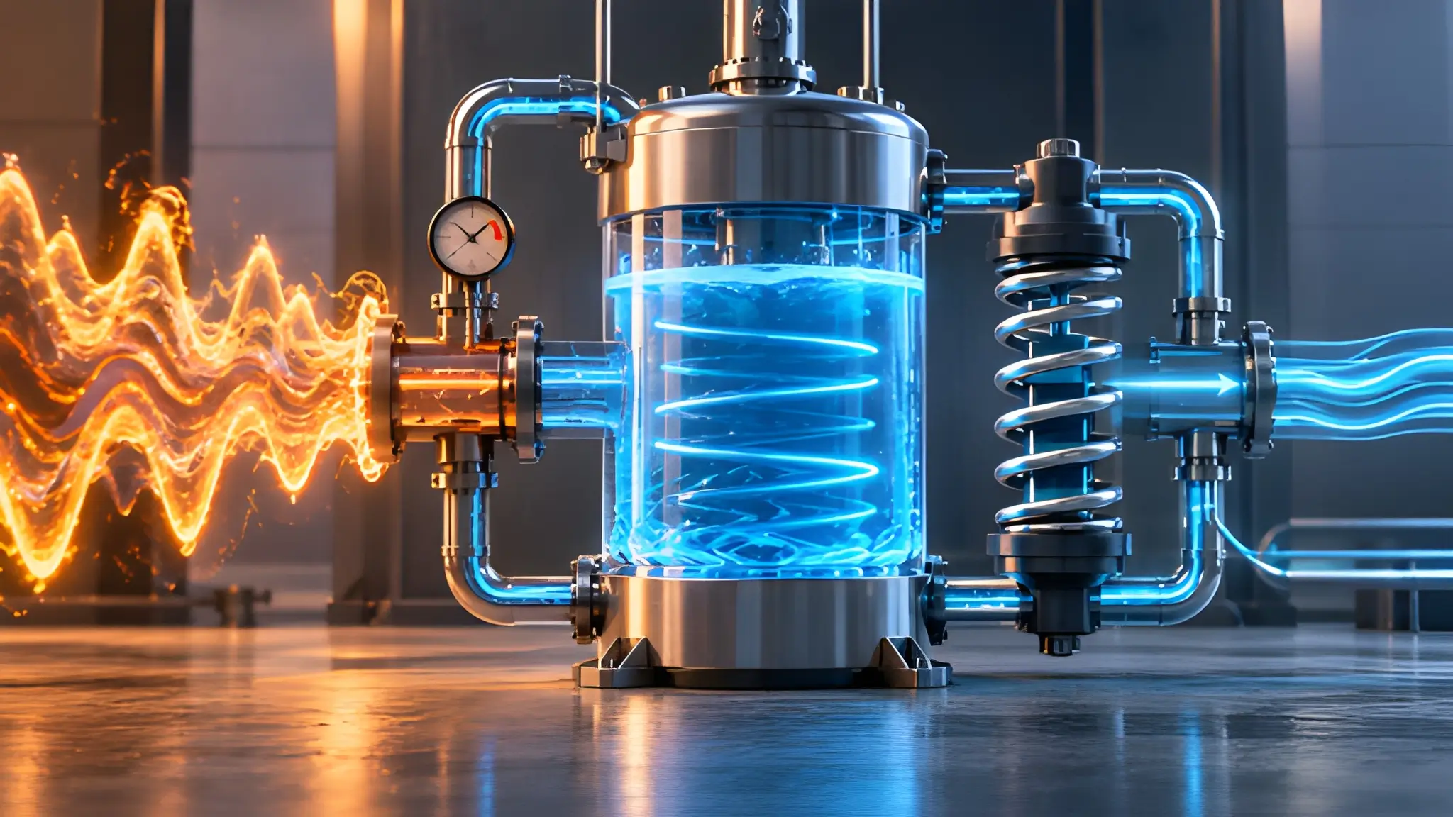
AI cooling failures are increasingly shaped by timing rather than simply by the amount of heat a system must reject. GPU workloads can change electrical and thermal demand extremely quickly, while the mechanical equipment ultimately rejects that heat operates through slower control and heat-transfer processes. Recent workload testing has documented highly transient GPU behavior, including rapid load changes that can occur on millisecond timescales. That creates a thermal-control problem because the heat arrives before the plant can necessarily change its operating state at the same rate. A coolant distribution unit can therefore serve as an intermediate layer between fast-changing chip loads and slower facility heat rejection. The engineering question becomes how much thermal disturbance the liquid loop can absorb before supply temperature, flow, or chip temperature moves outside its operating envelope.

The CDU matters because it separates the immediate thermal response at the rack from the behavior of the facility-side cooling plant. A liquid-to-liquid CDU transfers heat between a secondary coolant circuit serving the IT equipment and a facility circuit responsible for rejecting that heat. That architecture provides a controllable boundary where flow, temperature, pressure, and heat transfer can respond to changing rack conditions without requiring every plant component to react simultaneously. The secondary loop also contains a finite quantity of fluid, giving the system thermal mass that can temporarily absorb additional heat as its temperature rises. That stored capacity does not eliminate the heat load or replace the chiller; it changes the time available for the rest of the cooling chain to respond. For high-density AI halls, that time can become an operational design variable rather than an incidental property of the plumbing.
The Spike Isn’t The Problem, The Lag Is
The thermal spike itself is not necessarily a failure condition when the cooling chain has enough control range and thermal mass to absorb it. The harder problem appears when heat generation changes faster than pumps, heat exchangers, chillers, cooling towers, or controls can change their operating points. Electrical measurements can capture transient GPU behavior far faster than a conventional mechanical plant can materially alter its heat-rejection capacity. That mismatch means a rack may experience a rapid increase in coolant heat load while the facility-side system still operates close to its previous condition. A properly engineered secondary loop can bridge part of that timing gap by allowing coolant temperature to change gradually while the plant catches up. The result is not extra cooling capacity in the conventional sense, but additional response time between the heat event and the point at which the plant must fully accommodate it.
That response time should be treated as a measurable thermal-control envelope rather than an assumed benefit of liquid cooling. Engineers can evaluate the loop by examining coolant mass, specific heat, allowable temperature rise, baseline flow, heat-exchanger approach temperatures, and the plant’s response characteristics under the actual workload profile. The basic stored-energy relationship is straightforward: thermal capacity increases with fluid mass and specific heat, while usable ride-through depends on the temperature rise that the equipment can tolerate. A larger fluid volume therefore provides more stored thermal capacity for the same allowable temperature excursion, although it also increases system volume, charge, pump requirements, and maintenance implications. The useful design target is not maximum fluid volume, but sufficient thermal mass to keep the IT-side temperature within limits during the expected transient. That shifts CDU sizing from a simple flow-and-capacity exercise toward a time-domain analysis of the complete cooling chain.

Inference Bursts Break Differently Than Training Bursts
Training workloads often create coordinated activity across large GPU populations because distributed computation repeatedly synchronizes processors, memory, and networking operations. Inference traffic can produce a different thermal signature because demand follows user requests, application behavior, model routing, batching decisions, and changing traffic intensity. A large inference service can therefore produce workload-dependent bursts that may affect some GPU groups more heavily than others rather than creating one uniform thermal event across every rack in a cluster. One group of GPUs may accelerate sharply while neighboring equipment experiences a smaller change in operating point. That spatial variation matters because facility-level cooling measurements may not capture the full magnitude of a short-lived rack-level excursion. The CDU sits closer to the affected equipment, so its sensors and control loop can provide a more localized response to changing rack conditions before those changes become significant at the broader cooling-plant level.
Localized inference events also create a different control problem because the duration and location of the disturbance may vary from one workload interval to another. A plant sized around average utilization can maintain adequate total heat-rejection capacity while still allowing individual racks to experience undesirable coolant-temperature movement during short bursts. That is where secondary-loop thermal mass becomes useful because it can moderate the rate at which a local heat event changes the coolant condition. Flow control can then redistribute cooling capacity while the heat exchanger and plant-side equipment respond to the altered demand. This approach does not mean every inference burst requires a large storage vessel, because the required thermal mass depends on rack power, fluid properties, allowable temperature rise, flow arrangement, and event duration. The engineering objective is to prevent a transient workload from becoming a transient IT constraint before the cooling chain has time to stabilize.
Why Asia’s Air Changes How You Size a Thermal Capacitor
Asia does not present one uniform climate, but several major AI deployment markets combine elevated ambient temperatures with high humidity for substantial portions of the year. Those conditions influence heat-rejection equipment because condenser performance depends on entering air or water conditions, while evaporative systems depend strongly on wet-bulb temperature. Higher outdoor conditions can increase the temperature lift required from cooling equipment and reduce the operating margin available at a given design point. Humidity also changes the psychrometric conditions under which heat-rejection and air-side equipment operate, although the effect differs substantially between cooling architectures. Consequently, a thermal buffer should not use a generic regional value simply because a site sits in a warm climate. The buffer calculation needs to reflect the actual ambient design conditions, heat-rejection technology, equipment ratings, and allowable secondary-loop temperature rise.
Warm conditions become particularly important when the facility operates close to its available heat-rejection capacity during periods of high IT demand. A cooling plant that has less available headroom may have less capacity available to absorb a short AI workload event through rapid plant-side adjustment. The secondary loop can provide a controlled interval during which coolant temperature changes within an approved range while the facility-side system moves toward the new operating condition. Higher ambient conditions do not automatically mean that a site needs a larger CDU tank, but they can reduce available heat-rejection headroom and make transient analysis more important. Engineers should therefore evaluate buffer performance against representative hot-weather operating points rather than only annual average conditions. Site-specific ambient data, chiller performance curves, cooling-tower limits, heat-exchanger approaches, and IT thermal limits should all enter the sizing model.
Inside the CDU: Fluid Volume as a Battery for Heat
The simplest way to understand coolant volume is to treat it as temporary thermal storage rather than as passive plumbing. Water has a substantial specific heat capacity, so a known mass of circulating fluid can absorb a calculable quantity of sensible heat for a defined temperature increase. The stored energy can be represented as Q = m × cp × ΔT, where m represents coolant mass, cp represents specific heat capacity, and ΔT represents the permitted temperature rise. That relationship gives engineers a direct method for testing whether a proposed loop can absorb a defined transient without exceeding the coolant-temperature limit. A specific ride-through period should therefore never appear as a universal design specification without the corresponding heat load, fluid volume, and temperature-rise assumptions. The duration emerges from the relationship between transient heat input, fluid mass, heat capacity, and simultaneous heat removal.
Consider a transient in which the IT load temporarily exceeds the heat-rejection rate available at that instant. The coolant does not need to reject every additional watt immediately if its temperature can rise within the permitted operating range. A larger fluid inventory increases the amount of heat that can enter the loop before reaching that temperature limit, while a larger allowable delta-T provides additional storage capacity without necessarily increasing fluid volume. Flow rate also matters because it determines how quickly heated coolant moves through the heat exchanger and returns toward the IT load. Residence time alone, however, should not become the sizing metric because a slow-moving loop can increase temperature gradients and reduce control performance. The useful design exercise is to model mass, flow, heat capacity, heat-exchanger performance, allowable temperature rise, and plant response together.
Ride-Through Is The New Resilience
Cooling resilience for AI infrastructure increasingly needs a time dimension alongside capacity, redundancy, and efficiency. A system can have enough installed cooling capacity and still encounter a transient where the rack-side thermal response moves faster than the facility-side plant can compensate. That makes thermal ride-through a useful operational metric because it asks how long the IT-side system can remain within its approved thermal envelope during a defined disturbance. The answer depends on actual equipment behavior rather than a universal number, which makes measured workload testing more valuable than relying only on steady-state design calculations. CDU buffering can contribute to that response by providing thermal mass, controlled flow, heat exchange, and localized monitoring close to the computing load. The resulting resilience comes from coordinating the timing of heat generation and heat rejection rather than simply installing more nominal cooling capacity.
The next generation of AI cooling assessments should therefore examine what happens between one thermal operating point and the next. Operators can test transient loads, measure coolant-temperature movement, observe flow response, and establish the time available before a rack reaches its thermal limit. Those measurements can then inform fluid volume, allowable delta-T, heat-exchanger sizing, control logic, and plant-side response requirements for the actual site. Such testing also exposes whether a nominally redundant cooling system can absorb a rapid workload change without creating an unexpected thermal constraint. Efficiency remains important, but efficiency measured only at steady state cannot describe the full behavior of a cooling system serving volatile AI workloads. For C-level infrastructure decisions, the more useful question becomes how many controlled seconds the cooling chain can absorb before thermal volatility reaches the compute layer.











