
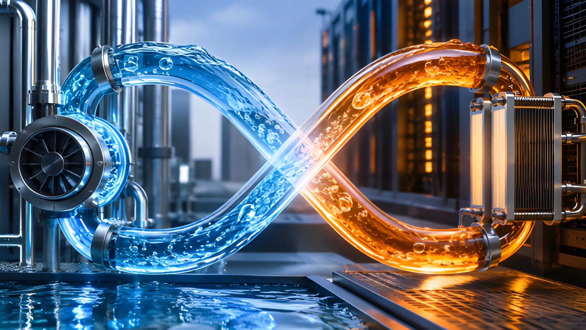
AI rack cooling now depends on a relationship between two liquid environments that should never behave like one system. Facility water carries the thermal burden toward the heat-rejection infrastructure, while the technology loop moves controlled coolant through cold plates and rack hardware. The heat exchanger sits between those worlds, but its role extends beyond transferring heat because it also defines where chemistry, pressure, contamination, and maintenance risk stop. A failure on one side should not automatically become a service event on the other side. That requirement becomes more consequential as rack thermal loads rise and cooling hardware moves closer to the equipment it protects. The question is therefore no longer whether liquid cooling can remove heat, but whether its architecture can preserve thermal service while individual components leave service.

Why One Loop Was Never Meant to Carry Both Worlds
A shared liquid path creates a common exposure that can turn an ordinary facility-side problem into a technology-side maintenance event. Facility water can experience changes in chemistry, suspended particles, corrosion products, or pressure conditions that do not suit a tightly controlled technology cooling system. The technology loop, meanwhile, must protect cold plates, narrow passages, fittings, pumps, and other wetted components whose material compatibility and fluid quality directly affect reliability. Keeping those fluids physically separate allows each loop to maintain operating conditions appropriate to its own components without forcing one chemistry regime across the entire cooling chain. A liquid-to-liquid heat exchanger provides that boundary while transferring thermal energy across separate fluid circuits. The architecture therefore treats separation as an active reliability mechanism rather than simply a convenient plumbing arrangement.
Pressure creates another reason to keep the two environments apart. Facility piping can operate under conditions that differ from the pressure envelope required by rack-side equipment, making pressure control across the heat exchanger an important part of system design. A pressure event on the facility side should not directly expose cold plates or rack manifolds to the same hydraulic condition. Particle carryover presents a similar problem because debris that remains manageable in a larger facility circuit can create restrictions when it reaches smaller passages inside technology cooling hardware. Fluid chemistry also changes over time through material interaction, contamination, additives, or makeup water, which makes long-term control more important than an initial commissioning test. Separation limits the number of ways those changes can propagate into the technology loop and gives operators a more controlled environment for managing coolant quality.
Paired Banks That Keep Thermal Service Live
Multiple liquid-to-liquid heat exchangers arranged in independently isolatable paths can create a different maintenance model from a single exchanger path when the remaining cooling capacity can support the connected load. In a properly engineered parallel configuration, multiple exchanger paths can share thermal duty while valves and controls allow one path to leave service without removing the entire cooling interface from operation. The active exchanger path can continue transferring heat between the facility circuit and the technology circuit while technicians inspect, clean, or service an isolated path, provided the remaining capacity stays within its design envelope. This arrangement separates the act of maintaining heat-transfer equipment from the decision to interrupt rack cooling. The practical value comes from the hydraulic path that remains available while equipment on the parallel path becomes inaccessible to the active circuit.

The paired-bank approach also changes how operators define usable redundancy. AA spare exchanger that requires draining, refilling, venting, balancing, and recommissioning before it can carry load does not provide the same operational value as a parallel path that can be isolated and placed into service within the system’s designed maintenance sequence. True service isolation requires more than installing additional plates because valves, controls, pressure management, flow measurement, and maintenance access must support the intended operating sequence. When one bank isolates, the remaining bank must maintain sufficient flow and heat-transfer capacity for the connected technology load within its design envelope. Operators can then inspect the isolated equipment without forcing coolant out of the active circuit or exposing the rack loop to repeated service handling. That approach makes the exchanger bank part of the uptime architecture rather than treating it as a replaceable component that sits outside the continuity strategy.
Isolation as a Contamination Firewall
Contamination control becomes more demanding when cold plates rely on small internal flow passages to remove heat from processors and accelerators. Particles, debris, biological material, and chemical residues can accumulate in liquid systems, while fouling can restrict passages and reduce effective heat transfer. A facility loop can therefore remain operational while still carrying conditions that the technology loop should not inherit. Physical separation prevents normal facility-water variability from becoming a direct technology-loop quality problem, while filtration and fluid monitoring provide additional controls within each circuit. The exchanger becomes the controlled interface where heat crosses between loops without allowing the fluids themselves to mix. In practical terms, that boundary acts like a contamination firewall around the rack-side coolant rather than relying on downstream filtration to repair every upstream problem.
Coolant stability also matters because thermal performance depends on more than temperature and flow rate. Changes in conductivity, additive concentration, corrosion products, dissolved contaminants, or material interactions can alter the condition of a closed technology loop over its operating life. A controlled secondary circuit gives operators a defined fluid environment to monitor and a clearer path for identifying changes before they affect rack hardware. Material compatibility remains important because copper, aluminum, stainless steel, polymers, seals, and other wetted materials can respond differently to a given coolant under different operating conditions. Keeping the facility circuit outside that chemistry envelope reduces the number of variables that operators must reconcile when diagnosing a technology-loop deviation. Consequently, isolation protects not only against visible contamination but also against gradual fluid-quality drift that can quietly undermine thermal reliability.
The New Normal: No-Drain Service Inside AI Halls
Maintenance becomes materially different when operators can isolate a heat-exchanger bank without draining the active technology circuit. Instead of treating every exchanger intervention as a cooling shutdown, teams can establish operating procedures around valve sequencing, flow confirmation, pressure checks, and thermal verification. The isolated bank can then undergo inspection while the active bank continues serving the connected load, provided the remaining capacity satisfies the system’s operating requirements. This model reduces the number of maintenance activities that require fluid removal, replenishment, air removal, and subsequent quality verification. It also limits unnecessary disturbance to a closed technology loop that operators have already conditioned and validated. The result is a maintenance strategy built around controlled isolation rather than repeated disruption of the coolant system.
Service continuity, however, depends on the complete operating sequence rather than the presence of two banks alone. Isolation valves must close reliably, instrumentation must confirm the intended flow path, and controls must recognize the reduced exchanger capacity before technicians begin work. Operators also need defined thresholds for temperature, pressure, flow, and differential pressure so that the active bank does not silently move outside its design envelope during maintenance. The technology loop should remain stable while the facility-side equipment undergoes intervention, which means the control strategy must preserve the hydraulic and thermal conditions required by the rack load. Such procedures also create a clearer boundary between facility maintenance and technology-loop maintenance because each team can work within a defined liquid domain. In turn, no-drain service can become a repeatable operating capability when the cooling system provides the required isolation, service access, controls, and remaining cooling capacity for that maintenance sequence.
When Isolation Stops Being Redundancy and Starts Being Architecture
Water isolation becomes architectural when the cooling system treats separation as a requirement that shapes valves, exchangers, controls, monitoring, maintenance access, and operating procedures from the beginning. A single shared path can transfer heat effectively, but it also concentrates chemistry, contamination, hydraulic, and service risk into one liquid environment. Separate facility and technology circuits establish a controlled boundary, while parallel exchanger paths can allow thermal hardware to leave service without necessarily removing cooling from the rack when the remaining path has sufficient capacity. The combination matters because redundancy without isolation can preserve capacity while still leaving the coolant environment exposed to a common failure mechanism. Conversely, isolation without serviceable parallel capacity can protect fluid quality while still forcing maintenance shutdowns. The stronger architecture addresses both conditions together by keeping the liquids apart and keeping a viable thermal path available.
A robust architecture should make that event predictable, bounded, observable, and recoverable without unnecessarily disturbing the technology coolant that protects the compute hardware. Parallel exchanger paths support that objective by allowing maintenance to occur against an isolated portion of the thermal interface while another path carries active service when the system has been designed for concurrent maintenance. The approach also gives operations teams a clearer framework for assigning responsibility, maintaining fluid quality, and validating thermal performance after intervention. As rack-level liquid cooling becomes more tightly integrated with high-value compute, those operational characteristics become part of the infrastructure design itself rather than secondary maintenance considerations. A useful benchmark for thermal architecture is therefore not simply how much heat an exchanger can move, but how effectively the system keeps separate liquid risks apart while preserving cooling service under defined maintenance conditions.











