Skip to content


The cooling decision that shapes an AI infrastructure site’s operating future often happens long before anyone installs a cold plate or connects a coolant distribution unit. It happens when the engineering team selects the temperature at which the liquid cooling system should operate. That choice appears ordinary because cooling specifications have traditionally treated colder water as a reliable way to protect computing equipment. Yet a lower supply temperature can impose requirements on the entire heat rejection system that persist throughout the site’s operating life. Chillers, heat exchangers, pumping arrangements, humidity controls, and heat recovery opportunities all respond to that initial temperature decision. A design that starts with unnecessarily cold water can therefore commit the site to mechanical complexity that the computing hardware may never have required.

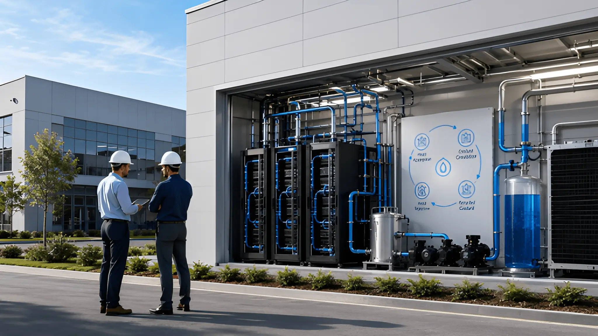
A 45C operating target illustrates how this approach can reshape decisions across the thermal chain without turning one temperature into a universal prescription. The relevant temperature must have a clearly defined measurement point, whether engineers mean coolant entering a cold plate, leaving a server, or reaching a secondary heat exchanger. Each location carries different implications for chip temperature, pumping demand, heat rejection capacity, and equipment compatibility. The cooling strategy succeeds only when the entire system supports the selected temperature through its intended operating envelope. A warm supply temperature cannot compensate for poor cold plate contact, insufficient flow, unstable controls, or an undersized heat rejection system. The value of the approach comes from coordinating those elements so the site rejects heat with less dependence on refrigeration and unnecessary water consumption.
The Cold Water Habit the Industry Never Questioned
Cooling infrastructure inherited much of its temperature philosophy from buildings where chilled water served air handling equipment and comfort cooling requirements. Those systems commonly relied on relatively cold water because air cooling depended on transferring heat through coils while also managing moisture in conditioned spaces. The equipment arrangements made sense for the loads they served, particularly where humidity control and air temperature requirements shaped mechanical design. Computing infrastructure adopted related approaches as server rooms and data halls expanded around air cooled hardware. Cooling engineers consequently developed familiar specifications around chilled water production, coil performance, and conservative supply temperatures. The resulting design culture often treated colder water as a straightforward source of thermal protection rather than questioning how much cooling intensity each workload actually required.
How Legacy Cooling Temperatures Became a Design Reflex
Liquid cooling changes the underlying heat transfer arrangement because the cooling medium reaches much closer to the components that generate heat. Instead of relying entirely on conditioned air to transport thermal energy away from electronic equipment, cold plates transfer heat into a liquid circuit through a comparatively direct thermal path. The fluid can absorb substantial heat while experiencing a controlled temperature rise, provided that engineers maintain adequate flow and suitable thermal contact. This arrangement gives designers more flexibility when selecting the coolant temperature than a traditional air cooling architecture might suggest. Yet project specifications can continue to reflect assumptions from systems where cold supply water served a different thermal purpose. When teams carry those assumptions into liquid cooled AI infrastructure without examining the actual component requirements, they risk retaining mechanical systems that no longer match the heat transfer architecture.

The habit becomes particularly consequential when engineers define the cooling plant before establishing the server side thermal operating window. A specification that begins with cold water can encourage chiller capacity, extensive hydraulic separation, and control arrangements intended to maintain temperatures that the computing equipment does not necessarily need. These choices create downstream dependencies because the cooling plant must support the original temperature assumptions even when the server technology changes. A site may consequently retain refrigeration equipment as an operating requirement rather than a contingency for exceptional conditions. The cooling design then limits the site’s ability to exploit ambient heat rejection despite having liquid cooled equipment that could potentially operate at warmer temperatures. The central engineering question should therefore concern the actual temperature and flow conditions needed at the heat generating components, not the temperatures that earlier cooling architectures made familiar.
Why Colder Water Can Create an Artificial Efficiency Boundary
The temperature entering a liquid cooling circuit influences much more than the immediate ability of a cold plate to absorb processor heat. It determines the thermal conditions that downstream heat exchangers and outdoor heat rejection equipment must maintain during operation. When engineers specify an unnecessarily low supply temperature, they narrow the range of ambient conditions that support compressor free cooling. A dry cooler may still reject heat during favorable weather, but its ability to maintain the required supply temperature depends on the available approach temperature. Lowering the coolant target reduces that margin and can increase reliance on mechanical refrigeration or other supplemental cooling methods. The resulting efficiency boundary reflects the interaction between the selected operating temperature and the heat rejection architecture rather than an unavoidable property of liquid cooled computing.
A cooling system that maintains unnecessarily cold water may also obscure the actual thermal capabilities of the installed computing equipment. Operators see stable inlet temperatures and acceptable processor behavior, but those observations do not establish that the equipment requires the selected coolant temperature. Determining the appropriate operating window requires examining processor limits, cold plate thermal resistance, flow distribution, coolant properties, and the conditions that accompany peak computational demand. Engineers must also consider residual heat that escapes into the surrounding air because liquid cooling rarely removes every source of heat inside a rack. These requirements make warmer water a coordinated engineering decision rather than a simple adjustment to an existing controller. Once teams establish the actual thermal operating envelope, they can evaluate whether the original chilled water specification provides meaningful protection or merely preserves an expensive design assumption.
45C Is a Setpoint You Choose, Not a Limit You Tolerate
A warm coolant target becomes strategically useful when the engineering team treats it as an intentional operating condition rather than the highest temperature the hardware can withstand. That decision begins with the thermal requirements of the processor, the cold plate, and the complete liquid circuit. Engineers must establish how much temperature difference the system can accommodate while maintaining acceptable junction temperatures under sustained computational load. They must also account for transient workloads, uneven flow distribution, fouling, and the changing performance of heat exchangers. A nominal supply temperature cannot establish these conditions on its own because the thermal resistance between the coolant and the silicon determines how effectively the circuit removes heat. The objective is to select an operating window that meets equipment requirements while giving the heat rejection system the greatest practical freedom.
Designing Around the Intended Operating Window
The difference between a maximum allowable coolant temperature and a deliberate design setpoint matters because each serves a different engineering purpose. A maximum allowable temperature defines a boundary that the system must not cross under specified conditions. An intentional operating setpoint establishes the conditions that the system aims to maintain during normal operation. When designers use the upper boundary as the everyday target without adequate analysis, they leave little room for unexpected thermal changes. When they instead choose a validated operating window, they can coordinate coolant temperature, flow, pressure, and heat rejection around a defined operating objective. The selected setpoint should therefore emerge from thermal analysis and equipment qualification, not from a desire to eliminate refrigeration at any cost.
A warmer supply temperature also changes how engineers evaluate the cold plate itself. The component must transfer heat effectively despite a smaller temperature difference between the coolant and the surrounding thermal interfaces. Engineers can address this requirement through cold plate geometry, channel design, flow distribution, contact pressure, and careful control of coolant properties. Each adjustment introduces tradeoffs involving pressure drop, pumping demand, manufacturability, and serviceability. A design that improves thermal transfer by increasing hydraulic resistance may create a new energy penalty in the pumping system. The best operating window therefore balances the temperature advantage of warm water against the complete hydraulic and thermal behavior of the installed equipment.
Making the Setpoint an Infrastructure Decision
The setpoint influences equipment selection before the site reaches commissioning. Heat exchangers, dry coolers, pumps, piping, control valves, and refrigeration equipment must all support the intended coolant conditions across the expected operating envelope. A design that targets warmer water can potentially use a different balance of heat exchanger surface area, outdoor heat rejection capacity, and mechanical cooling than a design that requires continuously chilled water. The exact equipment arrangement depends on local climate, heat density, coolant characteristics, redundancy requirements, and the temperature limits of connected equipment. Engineers must also evaluate how the system behaves during partial loads, startup, maintenance, and changes in outdoor conditions. These decisions make coolant temperature part of the site’s fundamental infrastructure architecture rather than a minor setting left to operations.
Procurement should reflect the same requirements by specifying the temperatures, flow conditions, pressure limits, and operating modes that suppliers must support. Vague language about compatibility with warm water can conceal different assumptions about measurement locations, coolant mixtures, maximum inlet temperatures, and allowable temperature variation. The specification should identify the relevant measurement points and require suppliers to document performance across the intended operating range. Acceptance testing can then establish whether the installed equipment meets the agreed thermal and hydraulic conditions. This approach reduces the risk that individual components satisfy their own specifications while the integrated system fails to deliver the intended operating performance.
Free Cooling Stops Being Weather and Starts Being Calendar
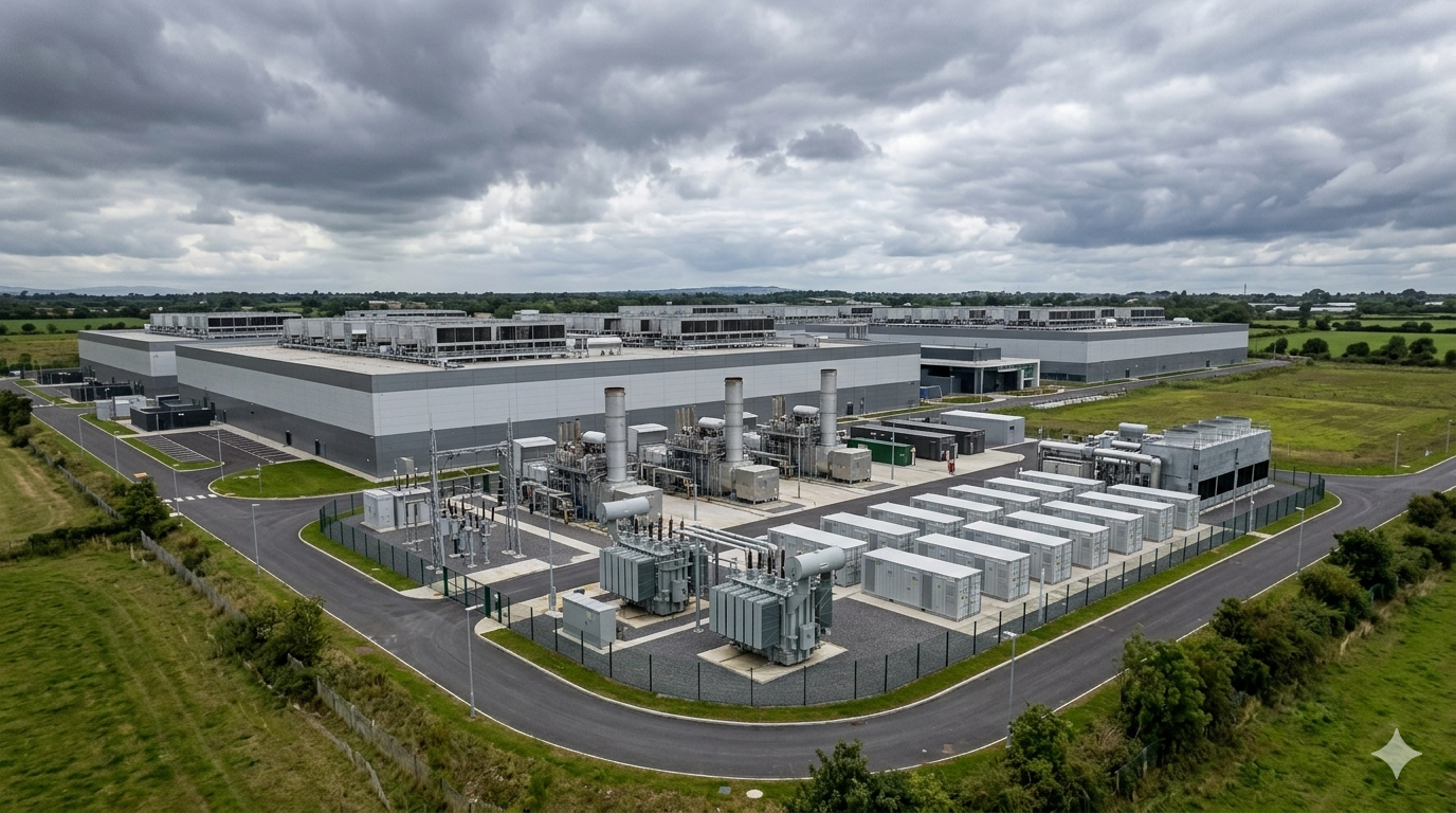
The economics of dry cooling change when the site no longer needs to produce chilled water as its default operating condition. A dry cooler transfers heat from the circulating coolant to outdoor air through a heat exchanger, without relying on evaporative water loss to reject that heat. Its ability to maintain the required coolant temperature depends on ambient conditions, heat exchanger performance, airflow, and the temperature difference between the liquid and the air. A cold water target can restrict this process because the outdoor air must remain sufficiently cool to support the required heat transfer. A warmer target creates a wider operating window in which the dry cooler can reject the computing load without mechanical refrigeration. The design question shifts from whether dry cooling can operate at the site to how the intended temperature window changes the periods when it can operate independently.
Turning Ambient Conditions Into Predictable Operating Hours
A site should evaluate free cooling as a seasonal operating resource rather than an occasional benefit of favorable weather. The engineering team can examine historical ambient conditions alongside the intended coolant supply temperature, expected heat load, heat exchanger approach, and required redundancy. This analysis identifies the conditions under which outdoor air can reject the site’s thermal load without compressor assistance. It also reveals when the cooling system needs mechanical support because ambient conditions, equipment limitations, or changing demand reduce the available heat rejection capacity. The resulting operating profile helps engineers compare cooling architectures using their expected modes of operation instead of relying on a single favorable design condition. A warm water strategy gains value when the site can plan around these operating periods while maintaining reliable cooling during less favorable conditions.
The annual operating profile also needs to reflect the difference between outdoor temperature and the temperature of the air entering the heat exchanger. Air recirculation, equipment placement, solar exposure, wind conditions, and exhaust discharge arrangements can alter the conditions that the dry cooler actually encounters. A site with favorable regional weather may still experience reduced heat rejection performance if the design allows hot discharge air to return toward the intake. Engineers must therefore assess the local airflow environment alongside weather records rather than treating regional climate data as a direct measure of equipment performance. They should also account for fouling, fan control, and the maintenance condition of heat transfer surfaces. This analysis turns free cooling from a broad climatic assumption into an operating strategy grounded in the site’s actual thermal conditions.
Treating the Dry Cooler as a Thermal Asset
The financial value of a dry cooler depends on more than its installed capacity or its ability to operate during a favorable weather condition. Engineers must consider the temperature window in which it can serve the site, the electrical demand of its fans, the resistance imposed by the heat exchanger, and the pumping requirements of the liquid circuit. A design that enables dry cooling but requires excessive airflow or pumping may simply transfer energy consumption from refrigeration to other components. The appropriate comparison therefore includes the complete cooling system rather than isolating the dry cooler from the equipment that circulates and conditions the coolant. Warmer water can improve the available temperature difference, but the design must still balance heat exchanger size, fan power, and hydraulic performance. A thermal asset earns its value through the work it can perform efficiently across actual operating conditions.
A robust design review should compare the dry cooler’s operating profile with the site’s long-term plans for computing capacity and equipment replacement. A future increase in rack heat density can change coolant flow requirements, heat exchanger loading, and fan energy even if the target supply temperature remains unchanged. New processor generations may also change the distribution of heat between liquid cooled components and residual air cooled loads. Engineers should test whether the planned dry cooling arrangement can accommodate those changes without forcing the site back toward a permanently colder operating target. The review should include expansion capacity, redundancy, controls integration, and maintenance access because these factors influence the system’s real operating availability. Treating the dry cooler as a strategic thermal asset connects today’s temperature decision with the site’s future flexibility.
The Return Temperature Is Where the Real Decision Lives
Supply temperature receives attention because it defines the conditions under which coolant enters the computing equipment. Return temperature reveals how effectively the system uses that coolant before sending it back toward heat rejection. The difference between those temperatures, commonly called the temperature rise or delta-T, reflects the relationship between the heat absorbed by the liquid and the amount of coolant moving through the circuit. Engineers can therefore use delta-T to understand whether a cooling architecture transfers heat effectively or circulates more liquid than the thermal load requires. A warmer supply temperature alone does not guarantee lower pumping demand because flow, pressure drop, and heat exchanger performance remain important. The stronger design objective is to coordinate supply temperature, return temperature, and coolant flow so that the complete system delivers the required thermal performance with minimal unnecessary work.
Designing the Temperature Rise Instead of Chasing a Cold Inlet
Consider a design in which coolant enters the cold plates at 25C and returns at 45C, compared with a design that enters at 32C and returns at 50C. Both examples describe possible operating conditions, not universal recommendations or proof that one arrangement will outperform the other. The first configuration has a larger temperature rise, while the second operates at a warmer inlet and a somewhat smaller rise. Engineers cannot determine the better design from those temperatures alone because the thermal load, coolant properties, flow distribution, cold plate resistance, and allowable component temperatures also influence performance. The correct comparison examines how much heat each circuit transfers, what flow it requires, and how much pressure the pumps must overcome. This shifts the design conversation away from inlet temperature as an isolated target and toward the relationship between temperature rise and total system energy.
A larger temperature rise also affects the design of heat exchangers because the returning liquid arrives with more thermal energy available for transfer to the next stage. Engineers must evaluate the hot-side and cold-side inlet conditions, required approach temperatures, available heat transfer area, and allowable pressure drop. A warmer return can improve the usefulness of the recovered heat, but the receiving circuit must be able to accept that heat at a compatible temperature. If the heat exchanger cannot transfer the required load under the intended conditions, the system may need more surface area, greater flow, or additional heat rejection capacity. Each adjustment affects capital requirements and operating energy in different ways. Delta-T becomes an architectural lever when designers evaluate these consequences across the full cooling circuit instead of optimizing one component independently.
Preventing Low Delta-T From Becoming an Operating Penalty
Low delta-T can indicate that a cooling loop circulates substantial coolant without extracting as much heat per unit of flow as the design intended. Several mechanisms can produce this condition, including bypass flow, control valves that allow excessive circulation, poor branch balancing, and heat transfer surfaces that fail to use the available temperature difference effectively. The condition can force pumps and heat rejection equipment to handle more flow than necessary, increasing electrical demand and complicating temperature control. A low return temperature may also reduce the usefulness of the coolant for downstream heat recovery because the circuit delivers less thermal energy at a useful temperature. Operators should investigate the underlying cause before increasing the supply temperature or changing pump settings. Correcting the hydraulic and control problem often matters more than changing the nominal temperature target.
The return temperature also helps determine whether a site’s heat rejection system operates as a coordinated thermal chain or as a collection of independently controlled components. If the cold plates, distribution piping, coolant distribution unit, and outdoor heat exchanger each follow different temperature assumptions, the resulting system may rely on mixing or bypass flow to reconcile incompatible conditions. Those arrangements can reduce the useful temperature rise and make control responses harder to predict. A coordinated design establishes how the coolant should behave at each interface and defines the control logic that maintains those conditions under changing loads. Engineers should verify the intended temperature profile during commissioning and investigate deviations rather than treating every temperature fluctuation as an isolated equipment issue. A stable return temperature then becomes an operating signal that connects component performance with the efficiency of the wider cooling architecture.
Above 40C, Waste Heat Finally Becomes Usable Heat
Heat leaving a computing system can serve as a useful energy resource when its temperature, available thermal capacity, and delivery profile meet the requirements of a suitable receiving process. A relatively cool waste heat stream may carry substantial thermal energy but still require additional energy before it can support a useful heating application. Raising the coolant temperature can improve the quality of that stream by making it easier to transfer heat into compatible processes. This changes the role of the cooling system from simply removing unwanted thermal energy to supplying a potential resource for another part of the site’s energy architecture. The opportunity becomes meaningful when engineers design the cooling and recovery systems together rather than treating heat reuse as an optional addition after commissioning.
Moving From Heat Rejection to Heat Recovery
A warm coolant circuit can support domestic hot water preheating, building heating, and selected industrial processes when its temperature and heat-transfer capacity match the receiving application’s requirements. The feasibility of direct reuse depends on whether the coolant temperature exceeds the receiving process temperature by enough to drive heat transfer through an appropriate exchanger. The exchanger must preserve separation between the computing coolant and the receiving circuit while providing adequate heat transfer capacity. Engineers also need to understand whether the receiving process requires continuous heat, intermittent heat, or a temperature profile that changes with demand. A warm return stream can support a useful recovery opportunity only when its supply conditions align with the recipient’s operating requirements. The design should therefore begin with a defined heat user rather than assuming that every available heat stream will find a suitable destination.
Industrial preheating offers another possible route because many processes need incoming water, air, or materials warmed before they reach their main heating stage. A recovered coolant stream may supply part of that thermal requirement, reducing the additional heat that the process must generate from another source. The suitability of this arrangement depends on the process temperature, the timing of demand, and the ability to maintain reliable heat transfer without contaminating either circuit. Some applications may accept the recovered heat directly, while others require a heat pump to raise its temperature before use. Engineers must evaluate the electricity consumed by that additional equipment against the useful heat delivered to the process. The resulting design should treat recovered heat as a managed energy input with defined quality and availability rather than as free energy.
Designing for the Recipient, Not Just the Source
District heating illustrates why a warmer coolant stream improves the opportunity for reuse without guaranteeing direct compatibility. A network may require a supply temperature above the temperature available from the computing loop, which creates a need for temperature upgrading through a heat pump or another suitable thermal process. That additional stage consumes energy and changes the economics of the recovery system. The site’s location also matters because nearby heating demand, network configuration, seasonal use, and the distance between the heat source and the recipient influence practical feasibility. Where demand disappears during warmer weather, the site needs a separate route for rejecting heat while maintaining computing operations. A viable recovery design therefore retains an independent heat rejection pathway and treats the receiving network as a valuable but potentially variable thermal load.
The control system must coordinate computing demand, coolant temperatures, recovery demand, and the capacity available from the heat rejection equipment. When a receiving process requests more heat than the computing system supplies, the recovery circuit cannot create additional thermal energy without drawing on another source or changing the operating conditions. When the recipient needs less heat, the site must continue rejecting the surplus without allowing coolant temperatures to rise beyond the approved operating window. Engineers can manage these conditions through controlled heat exchanger bypasses, temperature regulation, and an appropriately sized independent heat rejection path. The design should also address maintenance isolation so that a fault in the recovery circuit cannot compromise the primary cooling system. This separation preserves cooling reliability while allowing the site to recover useful heat whenever the receiving process can accept it.
Dew Point Is a Critical Constraint on Cold Surfaces
The minimum suitable coolant temperature depends on processor requirements, coolant specifications, heat-transfer performance, and environmental conditions that can create condensation on exposed surfaces. When a surface falls below the dew point of the air around it, moisture can condense on that surface and create an operational hazard. The dew point depends on both air temperature and relative humidity, so the risk changes as environmental conditions and air handling arrangements change. Cold pipes, exposed fittings, manifolds, and other components can encounter condensation even when the processor itself remains within its approved thermal limits. A warm water design can reduce this risk by keeping relevant surfaces above the local dew point under the conditions the system is designed to handle. The engineering objective is to establish a safe temperature margin across the complete installation rather than assuming that compliant silicon temperatures guarantee a safe cooling environment.
Managing Condensation Across the Complete Liquid Circuit
Condensation prevention requires engineers to evaluate exposed surface temperatures against the local dew point while also meeting the thermal limits and operating requirements of the connected equipment. A coolant temperature above the dew point at one measurement location does not automatically establish that every component remains safe throughout the system. Local temperature differences, stagnant air, insulation gaps, and changes in room humidity can create conditions that differ from those at the main coolant sensor. The design should identify vulnerable surfaces and provide suitable insulation, vapor barriers, humidity management, and temperature monitoring where needed. Engineers should also consider maintenance activities because opening an enclosure or changing airflow can expose previously protected surfaces to different moisture conditions. A reliable design combines an appropriate coolant operating window with physical protection and monitoring rather than relying on temperature selection alone.
A warmer coolant circuit can reduce condensation risk where it keeps exposed liquid-carrying components above the local dew point, although other cold surfaces and changing humidity conditions may still require protection. That advantage can reduce the need for aggressive environmental control solely to protect very cold surfaces, depending on the installation and the approved operating conditions. It does not eliminate the need to assess humidity, particularly where cold water remains in secondary circuits or where other equipment creates cold surfaces nearby. Operators should verify the expected dew point range and establish alarms for conditions that threaten the required surface temperature margin. The monitoring system should distinguish a genuine condensation risk from ordinary changes in coolant temperature that remain within the validated operating envelope. This approach supports operational stability by making moisture risk a measurable engineering condition instead of an unpredictable consequence of cold water operation.
Establishing the Operating Margin Before Commissioning
The dew point should enter the design process before engineers finalize piping routes, insulation details, control sequences, and room environmental requirements. A system that depends on exceptionally dry air to protect cold surfaces may require additional humidity control and monitoring throughout its operating life. A warmer design can reduce that dependency where the selected temperature keeps vulnerable surfaces safely above the expected dew point, but the team must verify the condition across startup, shutdown, maintenance, and fault scenarios. The assessment should include local air conditions around valves, couplings, distribution manifolds, and other exposed components rather than examining only the main supply pipe. Engineers must also verify the compatibility of insulation and vapor barriers with the expected operating temperatures and service conditions. The resulting design establishes condensation protection as part of the thermal architecture, not as a commissioning adjustment added after the cooling loop becomes operational.
Commissioning should demonstrate that the controls respond appropriately when humidity rises or coolant temperature changes. Engineers can verify sensor placement, alarm thresholds, insulation continuity, and the response of the system to expected environmental variations. They should also confirm that maintenance procedures preserve condensation protection when technicians disconnect equipment or expose normally enclosed components. An alarm that detects a condition only after moisture has formed provides less protection than a control strategy that identifies a developing risk and responds before the surface crosses the dew point. The operational documentation should explain which conditions require intervention and which remain acceptable within the approved design envelope. These measures help ensure that the benefits of warm water translate into reliable operation rather than a new set of poorly understood environmental risks.
Warmer Inlet Is How You Run Cooler Operations
A warm water cooling strategy brings the economics of heat rejection, the behavior of the hydraulic circuit, and the operating requirements of computing equipment into one design decision. The selected coolant temperature influences how long dry coolers can operate independently, how much refrigeration the site needs, and whether the returning heat can serve another purpose. It also affects pumping requirements, heat exchanger selection, condensation protection, and the complexity of the control system. None of these outcomes follows automatically from raising the inlet temperature because each depends on equipment compatibility and the conditions under which the site operates. The engineering value comes from choosing a temperature that works across the complete thermal chain instead of optimizing one component in isolation. A warmer inlet becomes a strategy when the entire infrastructure supports it as an intentional operating condition.
Staying Inside the Economic Boundary
The economic boundary emerges where the additional resources required to maintain a colder coolant temperature no longer deliver a meaningful benefit to computing performance or reliability. Refrigeration, pumping, humidity management, and heat rejection all contribute to the cost of maintaining the selected operating conditions. A warmer target can reduce some of these demands when the computing equipment supports it and the heat rejection system can exploit the additional temperature difference. Engineers still need to assess capital expenditure, electrical consumption, maintenance requirements, redundancy, and the consequences of equipment failure. The preferred operating window is the one that balances these factors while preserving the required thermal margin under demanding conditions. This evaluation prevents the site from confusing a lower coolant temperature with a universally better cooling design.
The avoidance zone begins when a design pursues warmer water without validating the limits of the installed equipment or the complete system. Insufficient cold plate performance, unsuitable flow conditions, incompatible components, and inadequate heat rejection capacity can undermine the intended benefits. The opposite mistake occurs when engineers preserve unnecessarily cold water requirements despite having equipment capable of operating within a warmer validated window. Both approaches weaken the relationship between the cooling architecture and the actual thermal needs of the computing load. A disciplined design process establishes the operating envelope, verifies the relevant component limits, and tests the system under realistic conditions before committing to the final architecture. This keeps temperature decisions grounded in engineering evidence rather than assumptions about either maximum heat tolerance or the inherent superiority of colder water.
45C is a Strategy
Thermal limits remain decisive because every cooling strategy must transfer heat away from the silicon at the required rate while keeping component temperatures within their approved operating limits. The coolant must absorb the thermal load, the cold plate must maintain adequate heat transfer, and the downstream system must reject or reuse the captured energy. A warmer supply temperature is viable only while the resulting component temperatures, flow requirements, and heat exchanger performance remain within the approved operating envelope. Engineers must preserve enough margin for workload changes, environmental variation, and equipment degradation without forcing the cooling system into unstable operation. That discipline separates a carefully engineered warm water architecture from a temperature target chosen primarily to reduce refrigeration demand. The objective is not to operate as warm as possible, but to operate at the warmest conditions that reliably satisfy the complete system’s requirements.
The decision to adopt a 45C warm water cooling strategy should begin during infrastructure planning, when engineers can still coordinate computing hardware, hydraulic design, heat rejection, and potential heat recovery. Procurement specifications should define the intended operating temperatures, flow conditions, pressure limits, and equipment performance requirements with enough precision to support integrated commissioning. Design reviews should test the system across seasonal conditions and realistic workload changes rather than relying on an ideal operating scenario. Operators should then verify the expected thermal behavior through measured supply and return temperatures, flow, pump demand, and heat rejection performance. This process creates a clear basis for deciding when dry cooling can carry the load, when mechanical assistance remains necessary, and whether recovered heat can serve a useful recipient. Warm water becomes an infrastructure strategy when the design, procurement, controls, and operating procedures all support the same thermal objective.