
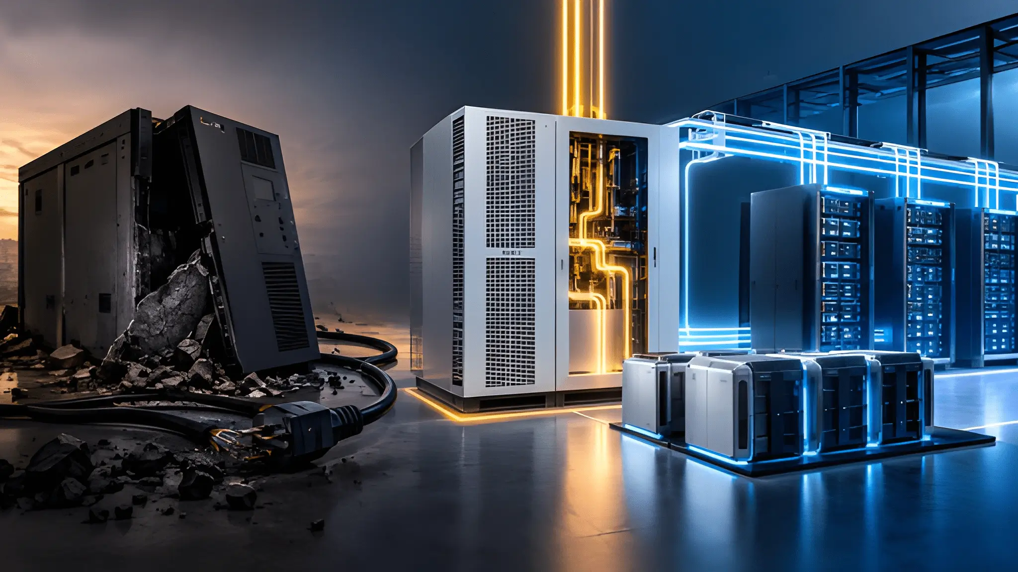
There is a moment in electrical architecture when a familiar component stops solving the problem it originally addressed. The component can remain highly engineered, highly reliable, and deeply embedded in operating procedures, yet the surrounding system can change enough to make its original function increasingly difficult to justify. That question is becoming more relevant for the conventional double-conversion UPS as AI infrastructure moves toward native high-voltage DC distribution. The important question is not whether an 800VDC system can connect to a UPS, because it can, but whether the UPS still offers the most direct way to control the fault and continuity problems that matter in a DC-native AI power chain. An 800VDC architecture changes where conversion occurs, where stored energy sits, where protection acts, and where engineers draw the boundary between utility power and compute power.

When the Power System Stops Thinking in AC
The change starts with the path electricity takes before it reaches the accelerator. In a conventional AI data center, utility AC passes through transformers, switchgear, distribution equipment, UPS systems, and rack-level power conversion before reaching the electronics that actually perform computation. Every conversion stage introduces control behavior, energy storage requirements, protection boundaries, and another collection of components that must coordinate during an abnormal event. An 800VDC architecture changes that sequence by moving the principal conversion from AC toward a high-voltage DC backbone, allowing the rack to receive DC directly rather than recreating an AC waveform before converting it back into DC. That does not eliminate power electronics, because the compute rack still needs downstream DC conversion for its internal voltage domains, but it removes one of the reasons for preserving an AC distribution architecture throughout the white space.
A DC-native architecture also changes the meaning of continuity. That capability made sense when the protected load expected AC and when the transfer between sources represented a meaningful electrical event. An 800VDC rack does not need an AC waveform at its input, so the central reliability problem shifts toward maintaining the DC link within the operating envelope required by downstream converters and compute electronics. The system therefore needs to answer a different question: how long can the DC bus remain within an acceptable range while another source or conversion path responds to the disturbance? That question leads naturally toward bus energy, converter control, solid-state isolation, and source coordination rather than toward a separate AC island sitting between the utility and the rack.
The Last Millisecond Lie the Double-Conversion UPS Was Selling
The conventional UPS solved a very specific problem that can become less important once the protected load becomes natively DC. Its inverter isolated the critical load from disturbances on the incoming AC supply, while its energy storage maintained the DC link feeding that inverter during source interruptions. The architecture therefore created an electrical island whose purpose was to keep the downstream AC waveform controlled even when the upstream waveform was not. That approach remains technically valid for loads that genuinely require an uninterrupted AC supply, but it creates an additional conversion boundary when the final load already operates through DC power electronics. For a purpose-built DC-native facility, the more direct the distribution path becomes, the less necessary it may be to create AC inside the continuity system before converting it back into DC at the rack.
That shift matters because the apparent urgency around UPS transfer behavior often hides a deeper requirement inside the rack. Compute electronics do not care about the philosophical continuity of the upstream AC waveform; they care whether their input converters remain inside their permissible voltage and current conditions. In the traditional chain, the UPS protects that condition indirectly by presenting a stable AC source to the rack power supplies. The rack power supplies then rectify and regulate that source before delivering the DC rails required by the compute system. A native 800VDC system removes the need for the rack to reconstruct the same AC relationship, because the rack receives a controlled DC input and performs the conversion required for its internal power domains. The fault that once appeared as an unacceptable AC disturbance therefore becomes a DC bus-management problem involving voltage collapse, current interruption, converter control, and source recovery.
The AC Waveform Was the Problem
The important consequence is not that every UPS disappears immediately, but that its location in the reliability chain becomes open to reconsideration. An AC UPS traditionally sits upstream of the rack because that is where it can protect a collection of downstream loads with a common conditioned waveform. A DC-native architecture can instead divide the same reliability responsibilities among source conversion, energy storage, DC protection, and rack-level conversion. This is where the architecture becomes more interesting than the individual equipment list, because a purpose-built DC-native system can distribute functions traditionally concentrated in the UPS across several power-electronic layers rather than reproducing them in another box. It is a coordinated set of controls and energy paths that can respond according to the location and character of the disturbance.

What the UPS Was Really Masking
At the rack level, the old architecture often hides the fact that several different electrical problems arrive through one AC interface. A voltage sag, a source interruption, a switching event, and a downstream short can all appear as disturbances against the same protected AC bus even though they require different responses. The UPS smooths that complexity by presenting a controlled output, allowing downstream equipment to operate without understanding the full electrical event upstream. That abstraction has enormous operational value, but it also means the protection system can become physically separated from the point where the fault originates. In a dense AI environment, that separation becomes increasingly significant because a high-power rack can impose substantial electrical stress on its local distribution path while remaining only one load among many on the upstream system.
The resulting architecture begins to redefine what ride-through means. Instead of asking how quickly an AC transfer can occur before the load notices the change, engineers can ask how the DC bus behaves during the disturbance, how much stored energy exists locally, how quickly the source converter changes operating state, and how selectively the fault can be isolated. Those questions connect the continuity function directly to the electrical topology rather than to a separate UPS subsystem. Capacitive energy on the DC link can support the bus during very short disturbances, while converter controls and upstream storage can address longer events that exceed the local energy envelope. A battery can still provide energy when the disturbance persists, but it no longer has to sit behind an AC inverter merely because the protected load happens to be connected to an AC distribution bus.
From Transfer Time to Hold Time: The New Definition of Ride-Through
Once the protected interface becomes DC, the most useful measure of immediate ride-through is no longer centered on an AC transfer event. The engineering problem becomes the ability of the DC link to preserve an acceptable voltage condition while the upstream topology determines what happens next. That places capacitance, converter control, source impedance, and fault isolation at the center of the continuity discussion. A DC link naturally stores energy, and that energy can support downstream converters during short disturbances without requiring an independent battery system to react to every transient. The amount of support available depends on the bus voltage, capacitance, allowable voltage excursion, load behavior, and the duration and shape of the disturbance. Engineers therefore have a direct physical relationship between the stored energy and the ride-through requirement instead of relying solely on an AC inverter and its downstream battery system.
That does not mean capacitor banks simply replace batteries in every application. Capacitors and batteries serve different electrical roles, and the distinction becomes especially important when the system experiences an event that lasts beyond the energy available in the DC link. Capacitive storage responds naturally to fast electrical changes, while battery storage supplies sustained energy through a controlled power conversion path. The new architecture can therefore use the DC link as the first continuity layer, the converter controls as the second response layer, and a larger energy-storage system as the source for sustained support. A grid-forming battery energy storage system can then operate as an active electrical source rather than merely as a battery connected to a conventional UPS inverter.
The DC Bus Becomes the Reliability Boundary
The deeper change is that the hold-up function can become distributed across the architecture. A disturbance that exists only for an extremely short interval does not necessarily require a battery to discharge, because the energy already present in converter links and bus capacitance can support the downstream load while the control system responds. A longer disturbance can require the source converter to draw from an energy-storage system, while the DC protection layer ensures that an unrelated fault does not consume that energy or collapse the common bus. This means the energy-storage system no longer has to be sized and positioned solely around the historical behavior of a UPS output. Its role can instead align with the broader electrical behavior of the site, including source support, islanding, recovery, and interaction with the utility connection.
Hold Time Becomes a Topology Question
The most important design decision therefore moves from the size of the UPS toward the placement of energy and the boundaries that control its release. If a rack fault occurs, the system should not interpret the event as a reason to support the fault indefinitely from a larger shared energy source. The local protection layer should identify the abnormal current behavior, isolate the affected branch, and preserve the remaining DC bus for healthy loads. If the upstream source disappears, the source-side converter and energy-storage system should respond according to the operating state of the wider electrical network. If the event remains confined to a short transient, the stored energy already present in the DC link can support the downstream converters while the system stabilizes. These responses depend on coordinated controls rather than on one device performing every continuity function.
This is where the concept of an integrated SST and DC distribution system becomes important. A solid-state transformer can perform controlled conversion between the medium-voltage AC system and the DC distribution layer while also providing an electronically managed boundary between the grid and the downstream load. Its power-electronic structure can coordinate voltage conversion, current control, and operating modes in ways that a passive transformer cannot. That does not mean the SST independently becomes a UPS, because the continuity function still depends on energy storage and control architecture outside the transformer itself. It means the principal conversion interface becomes an active component in the reliability system instead of a passive step between switchgear and downstream equipment. When coupled with energy storage and selective DC protection, the conversion stage can participate in the response to disturbances rather than simply passing them through.
The GFM BESS Takes Over Some Stability Functions
The disappearance of the conventional UPS does not mean that the AI power system becomes passive, because the functions once concentrated inside the UPS migrate into coordinated power-electronic controls distributed across the site. A grid-forming battery energy storage system can establish and regulate a voltage and frequency reference rather than waiting for an external AC waveform to define its operating point. That capability changes the relationship between the electrical source and the compute load because the energy-storage inverter can participate in maintaining the electrical environment instead of merely responding to disturbances after they occur. DOE and NREL research describes grid-forming inverters as resources that can support voltage, frequency, synchronization and system restoration, while also recognizing that their behavior differs fundamentally from synchronous machines.
Stability Moves to the Campus Edge
The old spinning-machine analogy remains useful only if it is handled carefully, because a GFM BESS does not reproduce physical rotational inertia or the unrestricted fault-current behavior of a synchronous generator. Instead, its controls can produce an inertia-like response by changing active and reactive power according to measured electrical conditions, while its battery provides the energy buffer required to sustain those actions. DOE research explicitly describes synthetic inertia as an inverter-enabled grid-support function, while NREL notes that inverter-based resources face physical limits on current, available DC-side energy and control behavior during faults. A GFM BESS can help establish voltage, support frequency and remain engaged through disturbances, but protection engineers still need to understand how much current the inverter can provide, how its controls behave during abnormal conditions and when it will deliberately limit or withdraw current.
That relocation also changes where operators should look when they investigate a disturbance, because the critical question is no longer simply whether the UPS inverter maintained its output waveform. The question becomes whether the site-level control system maintained the electrical conditions required by the SST, DC bus and compute converters while isolating the disturbance from unaffected branches. A GFM BESS positioned at the campus edge can therefore support the wider electrical environment while the SST handles conversion and electrical separation closer to the load. This division creates a layered response in which the BESS supports the source-side electrical system, the SST manages the conversion boundary, and downstream protection prevents a local DC event from becoming a site-wide disturbance. Research into inverter-dominated power systems increasingly treats these functions as coordinated system services rather than as isolated equipment capabilities.
Fault Current Stops Being a Simple Hardware Attribute
The hardest part of moving from conventional AC protection to inverter-dominated architecture is not generating a stable voltage reference, but deciding how the protection system recognizes and clears faults when the source itself controls its current. Traditional synchronous generators naturally produce substantial fault current because their electromagnetic and mechanical characteristics impose a different response to a short circuit. Inverter-based resources behave differently because their semiconductor switches, thermal limits and control algorithms can constrain current during a fault. NREL therefore identifies protection as a central engineering challenge for systems with increasing inverter penetration, noting that inverter fault current can be programmed and may differ significantly from the current signature expected by conventional protection schemes. For an AI site, that distinction matters because the GFM BESS cannot simply be treated as a drop-in replacement for every protective function previously associated with a conventional source or UPS.
The change becomes particularly important when the source-side BESS, SST and DC distribution are treated as one fault-management system rather than as independent products. The GFM BESS can maintain the electrical reference, the SST can regulate power transfer across its conversion boundary, and downstream solid-state protection can disconnect a damaged branch without forcing the entire DC network to collapse. None of these components can guarantee isolation by itself, because protection selectivity depends on detection, coordination, current limiting, energy absorption and the physical arrangement of conductors and converters. NREL’s protection research makes clear that inverter-dominated systems require different protection thinking because their fault-current behavior does not mirror synchronous generation. That means the new architecture does not eliminate protection complexity; it relocates that complexity into software-defined controls, converter boundaries and fast electronic switching.
The Solid-State Breaker Redefines DC Fault Isolation
The automatic transfer switch was built around a world in which the electrical system changed sources by physically switching an AC load from one path to another. That logic becomes less central when an AI site distributes power as DC and uses actively controlled conversion stages to maintain the required electrical conditions. A solid-state circuit breaker instead focuses on the more fundamental question of whether a specific electrical path should remain connected when its current or voltage behavior indicates a fault. Research on DC solid-state protection emphasizes this difference because DC systems lack the natural current zero crossing that simplifies conventional AC interruption. Semiconductor switching allows the protection device to act through controlled interruption rather than waiting for an AC waveform to pass through a favorable point in its cycle. That makes the breaker part of the power-electronic architecture rather than a passive mechanical endpoint positioned downstream of it.
Failover Becomes Fault Isolation
The important point is not that every mechanical breaker disappears, because galvanic isolation remains necessary for maintenance and safety in many architectures. Open Compute Project material on DC distribution explicitly describes solid-state and semiconductor breakers alongside mechanical contacts that provide galvanic isolation, showing that future DC protection can combine electronic interruption with physical isolation. The solid-state portion handles the rapid electrical event, while the mechanical portion can establish a visible and durable isolation state when personnel need to work on the circuit. This combination changes the meaning of an ATS because the system no longer depends on a mechanical device to perform every transition between normal and abnormal operating states. Instead, electronic protection can contain the event first, while slower physical isolation follows when the operating procedure requires it.
This is where the solid-state breaker becomes more than a faster version of an existing component. It becomes a local boundary that determines how much of the DC network is exposed to a fault before the system isolates it. IEEE research has demonstrated DC solid-state breaker concepts with response characteristics in the microsecond range, while newer hybrid approaches combine semiconductor interruption with current limiting and mechanical isolation to improve selectivity and reduce losses during normal operation. They do demonstrate, however, why electronic protection becomes strategically important when a DC architecture has little tolerance for uncontrolled fault-current growth. The breaker is no longer simply a component that opens after a relay decision; it can become part of the mechanism that shapes the fault itself.
Protection Moves Inside the Power Electronics
The shift to solid-state protection also changes how the site treats fault detection, because the breaker can receive electrical information from the same system that controls the converter. A conventional protection chain often separates measurement, relay logic and mechanical interruption into distinct devices with clearly defined interfaces. An electronic breaker can integrate sensing, decision logic, current limiting and semiconductor switching much more tightly. IEEE research on current-limiting solid-state breakers shows why this integration matters, particularly in DC systems where fault current can rise rapidly and where selectivity becomes difficult when line impedance is low. The protection system can therefore respond to the trajectory of the fault rather than waiting for a conventional overcurrent signature to mature. That creates an opportunity to protect individual power branches without requiring the upstream source to interpret every downstream disturbance.
Yet faster interruption does not automatically create a better protection system, because the speed of one breaker can make coordination harder if neighboring devices do not understand the same fault. DC systems have no natural zero crossing, and their low impedance can allow fault current to rise rapidly across multiple paths. IEEE research has specifically identified coordination and selectivity as major challenges for solid-state DC protection, particularly when several breakers operate within the same tightly coupled distribution network. The new architecture therefore requires protection zones, communication logic or local discrimination methods that prevent a downstream fault from triggering unnecessary upstream isolation. This requirement reinforces the importance of the SST because converter boundaries can provide additional electrical separation between sections of the site. The objective is not simply to interrupt faults quickly, but to interrupt the smallest possible fault domain while keeping healthy compute power paths energized.
The Hold-Up You Didn’t Need a Battery For
The most important change in ride-through architecture may be the realization that not every interruption requires a battery because not every disturbance represents an energy deficit that lasts long enough to justify chemical storage. An 800VDC system already contains electrical energy within its DC-link capacitors, converter stages and other local energy-storage elements. Those components can support the DC bus during very short disturbances while the upstream conversion system responds or the fault is isolated. The concept does not eliminate batteries from the site, because batteries remain valuable when the system must sustain power for longer disturbances or provide broader energy services. It instead separates instantaneous electrical continuity from sustained energy backup, allowing each function to use a different physical mechanism. That separation weakens one of the central assumptions behind the conventional UPS architecture: that the same equipment must both clean the waveform and store enough energy to bridge every interruption.
Stored Energy Moves Into the Conversion Chain
This distinction becomes clearer when the SST is viewed as an active power-transfer boundary rather than as a conventional transformer with electronics attached. The converter can regulate the DC output while its internal energy-storage elements participate in maintaining the bus during rapid changes in input or load conditions. The DC bus therefore becomes a controlled electrical reservoir whose behavior depends on capacitance, converter controls, source response and load characteristics. Open Compute Project work on 800VDC architectures identifies DC distribution, conversion and power smoothing as system-level concerns, reinforcing the idea that continuity can be addressed through the architecture of the power path rather than by adding an isolated UPS stage at the end of it. The key engineering question becomes how much disturbance the conversion chain can absorb before another energy source must respond. That question is fundamentally different from asking how large a UPS battery must be.
The result is a layered energy hierarchy in which capacitive energy handles the shortest electrical events, active converters manage the transition between power states, and BESS provides sustained energy when the disturbance exceeds the capability of the instantaneous layers. That hierarchy avoids using battery chemistry for every interruption and allows the battery system to operate according to the energy needs of the site rather than the waveform-cleaning requirements of individual racks. It also changes the failure modes that operators must monitor because capacitors, semiconductor switches and control loops become part of the continuity mechanism. The implication for AI infrastructure is that ride-through becomes a property of the complete conversion chain rather than a rating printed on a standalone backup cabinet. Once that happens, the question “Where is the UPS?” becomes less useful than “Where is the energy stored, how does it move, and which fault domain controls it?”
Ride-Through Becomes a Control Problem
The conventional UPS model makes ride-through relatively easy to describe because the battery sits behind a power converter and supplies energy whenever the upstream source falls outside the permitted operating envelope. A DC-native architecture distributes that responsibility across the source converter, DC link, local protection, rack converters and campus BESS. Each layer has a different job, and the system remains reliable only when those jobs are sequenced without creating competing control actions. A transient at the source should not automatically become a rack interruption, just as a rack fault should not automatically become a campus-wide energy event. The SST can provide electrical separation and regulated conversion, while the DC bus and its stored energy provide a local buffer against very fast changes. The GFM BESS then handles the broader energy and electrical-support problem when the disturbance extends beyond what the local conversion layers can absorb.
The deeper consequence is that ride-through becomes an architectural property rather than a product category. A site that relies on 800VDC distribution can design its continuity behavior around the interaction between SSTs, DC-link energy, SSCBs, rack converters and GFM BESS instead of inserting a separate AC UPS between the facility distribution system and the compute load. That approach does not guarantee uninterrupted operation by itself, because every converter, protection device, control loop and energy buffer introduces its own failure modes and coordination requirements. The engineering challenge therefore moves toward proving that the fault domains remain bounded and that each layer has enough control authority to respond without destabilizing another layer. The strongest architecture is consequently not the one with the largest backup device, but the one in which energy, conversion and protection are assigned to the electrical boundary where each function is most effective.
Splitting the Fault Domain: How SST Isolates a Rack Failure From a Campus Failure
The most consequential change in an 800VDC architecture is not simply the voltage delivered to the rack, but the number of electrical boundaries that can exist between the utility connection and the compute load. In a conventional AC hierarchy, multiple loads can share buses, switchgear and UPS output paths, which means a disturbance can propagate through equipment that appears electrically separate but remains connected through a common distribution path. An SST introduces an actively controlled conversion boundary that can regulate power between those domains rather than passing the upstream electrical behavior directly toward the load. That boundary gives the system another place to control voltage, current and energy flow before a disturbance reaches downstream equipment. DOE research on advanced power-electronic systems similarly treats converter controls, protection and fault behavior as interconnected parts of system resilience rather than as isolated equipment functions.
The Converter Becomes the Electrical Firewall
That does not mean an SST automatically prevents every rack fault from affecting upstream equipment, because fault isolation still depends on the complete topology, protection coordination and converter behavior. A short circuit downstream of an SST can still draw energy from the DC bus unless a coordinated protection system detects and isolates the affected branch. The important difference is that the SST creates a controllable boundary through which that energy must pass, giving the protection system another mechanism for limiting the disturbance. A solid-state breaker can operate on the downstream side while the converter controls the upstream relationship, allowing the fault domain to become narrower than the entire distribution bus. Research into inverter-based protection continues to emphasize that fault behavior depends on the interaction between source controls, protection devices and network topology rather than on the source rating alone.
This creates a fundamentally different relationship between a rack and the rest of the AI hall because the rack no longer needs to share every electrical characteristic of the upstream source. The converter can establish the conditions required by the downstream bus while limiting how directly disturbances on that bus couple back into the source-side network. The protection system can then treat a rack branch as a defined electrical zone instead of interpreting the rack event as evidence that the entire hall has become unstable. That separation is especially important when compute loads change rapidly, because the power system must distinguish ordinary load behavior from an actual electrical fault. GFM controls can support the broader electrical environment, but DOE research makes clear that grid-forming systems still require dedicated attention to protection, fault ride-through and recovery.
From Shared Bus to Bounded Failure
The old reliability model often treated redundancy as the addition of another complete power path, with the assumption that a second path becomes useful when the first path fails. A DC-native architecture can approach the same problem from a different direction by reducing the size of the electrical area that must fail together. The objective shifts from merely providing another source to preventing one local event from becoming a common event across multiple sources and loads. SSTs, SSCBs and controlled DC distribution can create nested fault domains in which a branch failure remains local while upstream conversion continues serving unaffected branches. This approach aligns with the broader direction of inverter-based protection research, which increasingly examines how protection zones and converter controls can preserve system operation when conventional fault signatures no longer provide the same information.
That approach also changes how redundancy should be interpreted by operators, because two physically separate feeds do not necessarily represent two independent electrical systems if they ultimately depend on the same conversion boundary or shared control layer. Independence has to exist across the relevant fault domains, including source conversion, DC distribution, protection, controls and energy storage. An SST can help establish that separation, but only when its upstream and downstream interfaces support the intended operating states during both normal operation and faults. GFM BESS can provide another source of electrical support, yet its inverter controls must remain compatible with the protection strategy rather than fighting it during abnormal conditions. DOE’s current work on grid-forming reliability explicitly includes system protection, inertia, stability and performance requirements because these functions become intertwined as inverter-based resources assume more responsibility.
What Dies With the UPS Box: The Skills, Spares and Single Points of Failure You Stop Buying
Removing the conventional UPS does more than remove a cabinet from the electrical room because the UPS has historically created an entire operational ecosystem around itself. That ecosystem includes battery strings, battery monitoring, bypass arrangements, static switches, UPS modules, maintenance procedures, replacement modules, service contracts and specialized troubleshooting practices. A DC-native architecture can eliminate or redistribute some of those functions because the power path no longer needs an AC UPS to reconstruct a stable load-side waveform between the source and the rack. The change is especially significant when short-duration ride-through comes from DC-link energy and converter control while sustained backup comes from a campus BESS. The system still requires energy storage and power conversion, but those resources no longer need to exist inside a dedicated UPS chain whose primary purpose is to protect an AC load.
The Physical UPS Ecosystem Starts to Shrink
That shift also removes some familiar single points of failure while creating new ones that operators must understand more precisely. A conventional UPS can concentrate substantial functionality inside one conversion path, meaning its power electronics, controls, bypass arrangement and energy-storage interfaces become tightly connected to the protected load. A distributed architecture spreads those functions across multiple electrical boundaries, which can reduce the consequence of one equipment failure but can also increase dependence on coordinated controls. DOE’s work on grid-forming inverter reliability illustrates the broader issue because inverter-based systems require common performance expectations, validation, modeling and protection coordination to behave predictably at system level. The new failure model therefore moves away from asking whether the UPS module is healthy and toward asking whether the source, converters, protection devices and controls remain synchronized in their intended operating states.
The maintenance regime changes with it because the most important inspection points are no longer concentrated around battery condition and UPS bypass equipment. Operators instead need visibility into semiconductor health, converter thermal behavior, DC insulation, capacitor condition, breaker operation, control firmware, communication paths and BESS availability. That does not make the new architecture maintenance-free, and it would be misleading to describe it as a simple reduction in maintenance burden. The work changes from maintaining a specialized continuity appliance toward maintaining an integrated power-electronic system whose components may sit across the campus. Research into grid-forming systems continues to identify modeling, controls, protection, testing and validation as essential requirements for reliable operation, reinforcing the need for a broader technical skill set. The operator who understands only traditional UPS maintenance would therefore have an incomplete view of the new reliability chain.
The New Failure Modes Need New People
The most important skills in the new architecture move toward power electronics, controls and DC protection because those disciplines determine how the system behaves when electrical conditions depart from normal operation. Engineers need to understand how an SST regulates its output, how an SSCB detects and interrupts a fault, how a GFM inverter responds to voltage disturbances and how stored energy moves between the BESS and the electrical network. They also need to understand the interactions between those functions because a protection action can change the electrical conditions seen by a converter, while a converter control action can influence how protection interprets a fault. DOE’s grid-forming research explicitly identifies system protection, control interoperability, fault behavior and modeling as unresolved technical areas requiring continued development. The operational skill set therefore becomes more interdisciplinary because reliability depends on the behavior of several tightly coupled power-electronic systems.
The spare-parts strategy changes as well because the traditional inventory centered on UPS modules, batteries and associated switching equipment no longer describes the complete reliability chain. The critical inventory can instead include converter power modules, control electronics, protection devices, sensors, communication interfaces, cooling components and BESS subsystems. Some of these components may have longer procurement cycles or require specialized diagnostic knowledge, which means operators cannot assume that removing the UPS automatically reduces supply-chain exposure. The stronger approach is to identify which components can create a common failure across a fault domain and which can be isolated without affecting unrelated electrical zones. That analysis connects spares strategy directly to topology because the operational consequence of losing one component depends on how many loads share its electrical boundary.
Uptime Without a UPS Room
The central change in the 800VDC AI power architecture is that continuity no longer needs to begin with an AC UPS and work outward toward the rack. The system can instead begin with the electrical boundaries that the compute load actually requires and assign energy storage, conversion and protection to those boundaries. A GFM BESS can support the source-side electrical environment, the SST can regulate and separate power domains, the DC link can provide short-duration stored energy, and SSCBs can contain faults before they spread across larger sections of the distribution system. DOE research into grid-forming systems supports the broader principle that inverter-based resources can provide voltage and frequency functions traditionally associated with conventional generation, while also emphasizing that protection and interoperability must evolve with those capabilities.
Reliability Becomes a Property of the Topology
The strongest version of this model does not claim that every AI site should immediately eliminate UPS systems, because legacy AC infrastructure, operating requirements, protection practices and equipment compatibility can still make conventional UPS systems appropriate. The more defensible thesis is that a purpose-built DC-native AI site can place the functions traditionally associated with the UPS into a coordinated set of power-electronic layers. The BESS supplies stored energy when the disturbance requires sustained support, while the SST and DC-link architecture handle electrical conversion and short-duration continuity closer to the load. The SSCB provides the local fault boundary, while higher-level controls coordinate the behavior of the source, converters and protected loads. DOE research continues to treat protection, fault ride-through, system stability and inverter controls as linked engineering problems, which reinforces the need to evaluate this architecture as a complete electrical system rather than as a collection of replacement products.
That logic also explains why the phrase “UPS replacement” can become misleading because the architecture is not replacing one box with another box. It is redistributing the functions that the box previously concentrated into the electrical network itself. Ride-through moves toward DC-bus energy and converter control, source support moves toward GFM BESS, failover moves toward solid-state protection, and fault isolation moves toward deliberately bounded converter and distribution domains. Each function remains dependent on the others, so the reliability of the system ultimately depends on whether their controls and protection decisions remain coordinated under abnormal conditions. DOE’s current grid-forming work shows that the industry is still developing the standards, models, validation methods and protection practices required for widespread inverter-based operation.
The AI Campus Becomes One Fault System
The final architectural shift is therefore from equipment-centered reliability to fault-domain-centered reliability, where every major component exists partly because of the electrical boundary it controls. The GFM BESS establishes a controllable source-side reference, but it does not become the universal answer to every fault. The SST manages the conversion boundary, but it does not replace selective protection. The SSCB isolates the affected branch, but it does not provide the energy needed to sustain the site through a prolonged source disturbance. The DC bus provides local stored energy, but it does not remove the need for broader energy storage when the disturbance lasts beyond its natural capability. Those boundaries create a system in which each component has a defined responsibility, and reliability emerges from their coordination rather than from the presence of one dominant continuity device.
A dedicated UPS room may no longer be required in a purpose-built DC-native architecture when the functions traditionally concentrated there are deliberately distributed across the electrical system. That does not make the new system simpler, and it does not make batteries, protection equipment or power electronics optional. It means the reliability strategy has moved from a dedicated AC continuity layer into a coordinated combination of GFM BESS, SST conversion, DC-link energy, SSCB protection and bounded fault domains. The result is a power system designed around the behavior of AI compute rather than around the historical assumptions of AC distribution. DOE research into grid-forming systems shows that this broader transition is still an active engineering field, with unresolved questions around protection, controls, interoperability and system behavior that must be addressed through modeling, testing and standards.











