Skip to content


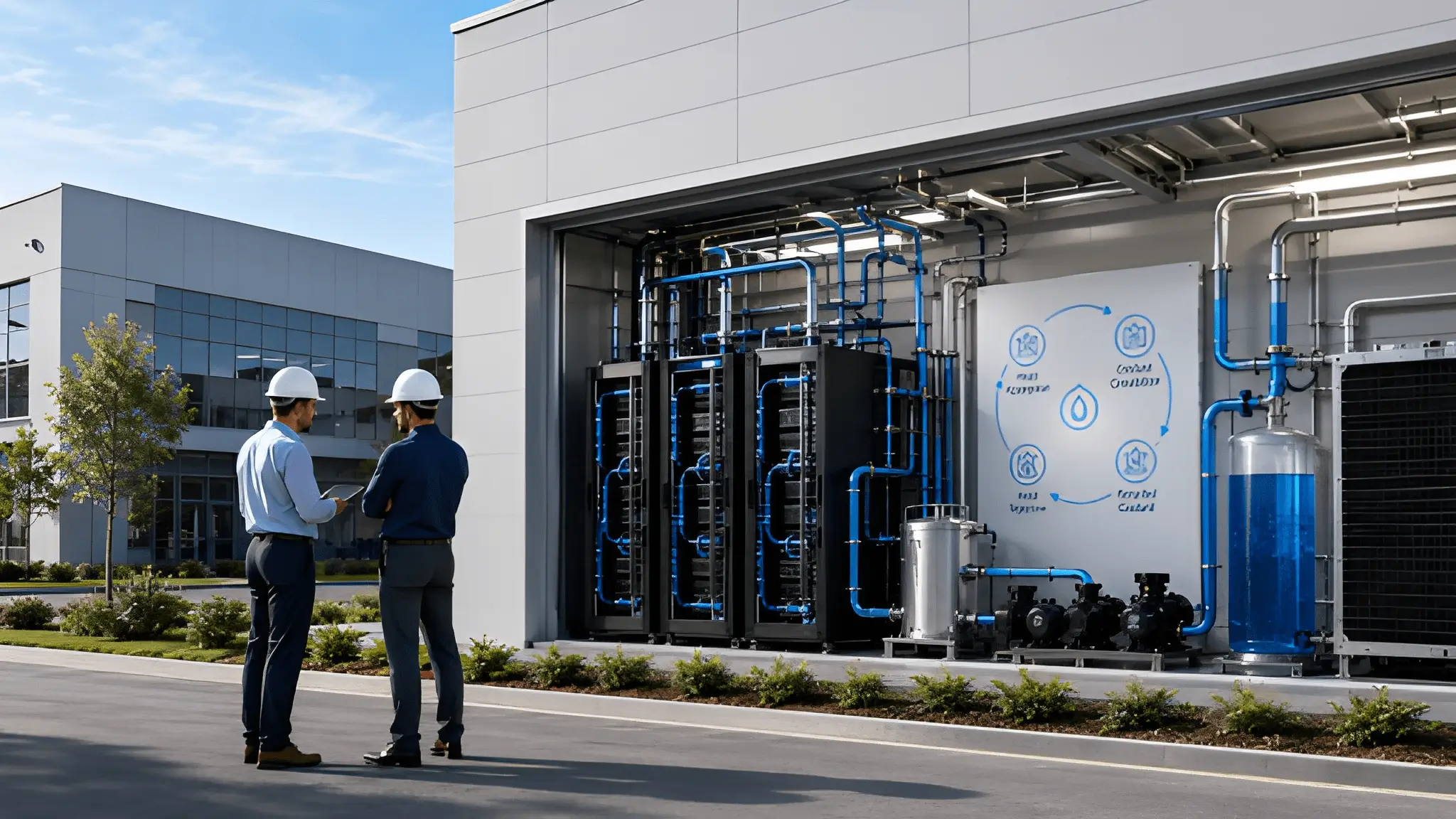
As a site expands, introduces new compute workloads, or adds cooling systems with different heat-transfer requirements, operators may encounter inconsistent monitoring interfaces and control practices if they have not defined common integration standards. A coolant distribution unit (CDU) can regulate liquid supplied to cold plates, a rear-door heat exchanger (RDHx) can remove heat from rack exhaust, and an immersion system can transfer heat from submerged equipment into a circulating dielectric fluid. When engineers select components independently for each cooling product without coordinating interfaces and qualification requirements, technicians may face multiple diagnostic procedures, separate replacement inventories, and control behaviors that complicate maintenance across the site. Building intelligence into cooling architectures therefore starts with a different engineering question: which elements must remain specific to the cooling method, and which can become common building blocks without compromising safety or performance?

The answer does not require operators to impose one mechanical design on every thermal system, nor does it mean that all cooling loops should use identical operating limits or control sequences. It requires a consistent intelligence layer that can accommodate different sensors, fluid properties, actuator characteristics, and failure responses while preserving a common engineering and maintenance approach. That layer can standardize selected measurement interfaces, processing capabilities, motor-control functions, communications, diagnostics, and power-conversion principles, even when each cooling architecture retains its own pumps, valves, heat exchangers, and fluid-handling requirements. A common component becomes useful when it performs a sufficiently similar function across applications, meets the relevant environmental and electrical requirements, and allows the control software to account for application-specific behavior.
One Intelligence Layer Across Multiple Cooling Architectures
The cooling architecture at a site often reflects the history of its compute environment rather than a single decision made at the beginning of its development. Existing racks may continue to rely on air movement and rear-door heat exchange, newer workloads may require direct liquid delivery to cold plates, and specialized deployments may use immersion to place equipment in contact with dielectric fluid. Those arrangements can coexist because they address different equipment configurations, service requirements, heat-transfer paths, and deployment constraints. Their mechanical differences do not eliminate the common need to detect abnormal operating conditions, regulate heat removal, preserve equipment protection, and communicate actionable information to operators. A shared intelligence layer can support those functions through reusable sensing interfaces, processing platforms, control modules, and diagnostic conventions while allowing each architecture to retain its own validated thermal and hydraulic behavior.
Common Building Blocks Without Identical Cooling Hardware
A common intelligence layer begins by separating reusable electronic functions from the mechanical assemblies that perform heat transfer, circulate fluid, or move air. A pressure sensor interface, temperature acquisition circuit, communications controller, and embedded processor can share a design approach across cooling systems, provided each implementation satisfies its measurement range, electrical protection, environmental exposure, and response requirements. Motor-control electronics can also follow common design principles while accommodating the different torque, speed, and feedback needs of pumps, fans, and actuated valves. This approach lets engineers standardize component families, connector conventions, firmware practices, diagnostic records, and service procedures without assuming that one complete controller can operate every asset unchanged. The engineering work lies in defining a reusable platform with explicit application boundaries, rather than producing a universal device whose capabilities cannot satisfy the demands of each installation.

The value of common building blocks becomes clearer when a replacement requires more than swapping a failed component. If each cooling product uses different sensor wiring, incompatible control electronics, and unrelated diagnostic conventions, technicians must identify the equipment family before they can even establish the correct maintenance procedure. A shared platform can help reduce that fragmentation by standardizing signal interfaces, configuration records, fault reporting, and selected components across applications that meet documented compatibility and qualification requirements. Engineers must nevertheless preserve the differences that affect safe operation, including fluid compatibility, operating temperature, pressure limits, sensor placement, actuator sizing, and the response required when a measurement becomes unreliable. A temperature sensor selected for one loop cannot automatically serve another merely because both controllers accept the same electrical signal. Standardization succeeds when it removes unnecessary variation while keeping the application-specific information that technicians need to diagnose failures accurately.
A Shared Control Model for Different Thermal Behaviors
A common control model should describe how the system measures its condition, evaluates demand, commands an actuator, and verifies the result without prescribing identical control sequences for every cooling method. A CDU may regulate coolant supply conditions and distribution pressure, while an RDHx system must coordinate liquid flow with heat captured from rack exhaust and the surrounding airflow. An immersion installation must account for the behavior of its dielectric fluid, the circulation arrangement, and the heat-transfer interfaces designed for submerged equipment. These systems can share a structure for sampling measurements, checking signal validity, recording operating states, and escalating faults, yet each requires its own limits and control response. Engineers can therefore reuse software modules for data acquisition, plausibility checks, communications, and event logging while keeping thermal control logic configurable and independently validated for the intended application.
This separation also helps maintenance teams distinguish a common component failure from a cooling-specific operating problem. If several systems report an implausible temperature signal, technicians can begin with a consistent diagnostic process for wiring, signal integrity, configuration, and sensor health instead of learning a completely different procedure for every product. If a pump loses its expected flow response after a speed command, the shared diagnostic framework can compare commanded speed, feedback, pressure, and measured flow while the application-specific logic determines the appropriate protective action. The framework should preserve raw measurements and relevant operating context so that a common alarm does not conceal different physical causes. It must also identify the affected loop and equipment boundary clearly, since a site-wide alert without precise localization can delay the response even when the underlying detection works correctly.
Designing the Inventory Boundary Around Function
The inventory strategy should begin with a functional classification of the components that operators expect to maintain across cooling architectures. Engineers can group candidate components by their role in measurement, processing, actuation, communications, and power conversion, then determine which characteristics must remain common for a replacement to work safely. A temperature acquisition module, for example, may qualify for reuse across several applications when its input range, isolation, accuracy, connector, and environmental ratings satisfy every intended installation. A motor-control module may share a hardware platform while requiring different firmware configurations, feedback interfaces, and protective limits for a pump and a fan. The inventory team should record those boundaries explicitly so that a common part number does not conceal incompatible configurations or create uncertainty during an urgent repair.
A well-defined inventory boundary also prevents standardization from becoming an exercise in reducing part numbers at the expense of reliability. Some components will remain architecture-specific because their wetted materials, mechanical dimensions, operating conditions, or safety requirements differ too substantially for common use. Other components can share a platform but still require application-specific calibration, parameter sets, or qualification records before technicians install them. Operators should therefore distinguish between a genuinely interchangeable spare, a common hardware platform that requires configuration, and a component that only shares a broad functional purpose. That classification gives procurement teams clearer substitution rules, supports consistent maintenance documentation, and helps engineering teams identify opportunities to consolidate components without compromising application-specific requirements.
Standardizing on Linear Flow Control at the Tray Level
The next step in building intelligence into cooling architectures is to make flow regulation more precise without turning every cooling assembly into a separate control and maintenance category. A liquid-cooled rack contains multiple thermal loads, and those loads may not demand identical coolant flow throughout their operating cycles. A conventional on-off valve provides a straightforward way to open or close a passage, but it offers limited control over intermediate flow conditions unless the wider system adds other regulating mechanisms. A modulating valve can adjust its opening across a usable range, allowing the control system to respond to changing thermal demand, hydraulic conditions, and equipment operating states. Modulating valves can support flow regulation closer to the load when the hydraulic design, available pressure, instrumentation, and control strategy support stable operation at that level.
Tray-level control does not mean that every server tray automatically needs its own motorized valve, nor does it guarantee that individual tray isolation will suit every hydraulic design. Engineers must first establish whether the distribution manifold, branch geometry, pressure available at each connection, and equipment manufacturer’s requirements support independent regulation. The control strategy must also account for minimum flow requirements, transient loads, valve authority, and interactions between neighboring branches. If a valve closes too far, it can increase the pressure available to other branches or push a shared pump into a less favorable operating region unless the system accounts for the resulting hydraulic change. A common linear-control building block can support different implementations, but the surrounding hydraulic design determines whether the result delivers stable regulation and useful fault containment.
Moving Beyond Binary Valve Commands
An on-off valve follows a simple operating principle: the actuator moves the valve toward an open or closed position in response to a control command. That arrangement can work well where a branch needs straightforward isolation or where the wider system controls temperature and flow through other mechanisms. Problems arise when the application requires continuous adjustment but the available valve behavior supports only coarse changes in the flow path. Repeated opening and closing can create fluctuations in branch flow, while a controller that reacts too aggressively may repeatedly correct conditions that have not yet stabilized. Engineers can address these behaviors by selecting a valve and actuator suited to the required modulation range, then tuning the control loop around the actual response of the hydraulic system.
A linear valve provides a commandable opening position across its operating range, but its position does not necessarily correspond to an equal percentage change in actual flow. Flow depends on the valve’s inherent characteristic, the pressure difference across it, the resistance of the connected branch, and the behavior of the rest of the circuit. Engineers must therefore distinguish between a valve’s mechanical travel and the effective flow characteristic that the complete installation produces. A controller may request a particular opening, yet the resulting flow can differ as other branches change their demand or the pump adjusts its operating point. Proper valve sizing, differential-pressure management, sensor placement, and control-loop commissioning determine whether the available modulation translates into useful regulation at the load.
Controlling Flow Closer to the Thermal Load
The location of a control valve determines which part of the cooling system can respond independently to a change in demand. A valve at the distribution unit can influence an entire supply circuit, while a valve on a rack branch can regulate that branch without necessarily giving technicians control over each downstream load. A tray-level arrangement moves the control boundary closer to the equipment, provided the manifold design and available pressure support the additional branches and actuators. Where branch-level sensing and independent valve control are available, this arrangement can help operators investigate localized flow restrictions or thermal changes without treating the complete rack as the smallest controllable unit. Engineers must still validate the resulting hydraulic behavior because smaller control zones introduce additional interactions, instrumentation requirements, and possible failure points.
The service benefit depends on how engineers coordinate regulation, isolation, and monitoring rather than simply adding more valves to the manifold. If a tray develops an abnormal thermal condition, the control system should correlate its flow measurement with inlet temperature, outlet temperature, pressure, and the operating state of the associated equipment. Where the hydraulic design permits independent isolation, technicians may be able to restrict work to the affected branch instead of draining or shutting down a larger portion of the rack. That outcome requires suitable isolation hardware, accessible service connections, validated recovery procedures, and clear identification of the affected flow path. A modulating valve alone cannot guarantee continued operation because shared manifolds, common pumps, electrical dependencies, and upstream faults may still require a broader intervention.
Eliminating the Sensor as a Leak Point
Every instrument installed directly into a coolant circuit introduces an interface that engineers must consider during design, commissioning, and maintenance. An inline flowmeter may provide a suitable measurement method, but its body, seals, fittings, and installation requirements become part of the pressure boundary and the fluid-compatibility assessment. Those interfaces do not automatically make inline measurement unsuitable, because properly selected and maintained instruments can operate reliably within their specified conditions. The engineering question is whether a particular measurement requires direct fluid contact or whether a non-invasive method can provide the information needed for control and diagnostics. Clamp-on ultrasonic flow measurement offers an alternative by using transducers mounted on the outside of a compatible pipe to infer flow from acoustic signals, avoiding an additional wetted sensor body in the measured section.
Measuring Flow Without Opening the Coolant Circuit
Clamp-on ultrasonic instruments generally use acoustic signals transmitted through the pipe and fluid to estimate flow, with the measurement method depending on the instrument design and operating conditions. Transit-time systems compare the travel times of signals moving with and against the flow, using the difference to estimate fluid velocity under suitable conditions. The instrument then applies the relevant pipe geometry and fluid assumptions to derive a flow value, which the control system can compare with its operating targets. Because the transducers sit outside the pipe, the measurement can avoid inserting a separate sensing element into the flow path or creating another wetted connection solely for instrumentation. However, the technique still requires a compatible pipe, suitable acoustic coupling, correct transducer positioning, and configuration that reflects the actual installation.
The suitability of clamp-on measurement depends on the pipe material, wall thickness, diameter, fluid properties, temperature, flow profile, and the presence of conditions that interfere with acoustic transmission. Pipe coatings, deposits, poor coupling, unsuitable straight-run conditions, and bubbles can affect the quality of the measurement, depending on the instrument and installation. Engineers should verify the manufacturer’s application limits and establish an appropriate commissioning procedure rather than assume that an external sensor will measure every coolant circuit accurately. The installation should also provide stable transducer mounting and sufficient access for inspection, since movement or deterioration of the acoustic interface can undermine repeatability. Non-invasive measurement removes a particular category of wetted instrument interface, but it does not remove the need for installation discipline, calibration checks, and diagnostic validation.
Treating Measurement Integrity as a Maintenance Requirement
The absence of a wetted sensor body does not make a flow measurement inherently reliable, because the control system still depends on the integrity of the acoustic signal and the validity of its configuration. A controller should identify an invalid or degraded measurement and distinguish it from a credible indication of low flow. That distinction matters because an erroneous low-flow reading could trigger an unnecessary protective response, while an undetected measurement failure could conceal a genuine restriction in coolant delivery. Engineers can combine signal-quality information, operating-state checks, and comparisons with related measurements to determine whether the reported flow value remains suitable for control. When the sensor cannot provide a trustworthy result, the system should follow a predefined fallback strategy rather than treat the last available value as indefinitely valid.
Sensor placement also affects whether the measurement helps technicians locate a fault or merely confirms that a larger circuit has changed. A flow reading at a common supply header can indicate a system-level condition, but it may not reveal which downstream branch has developed a restriction or lost circulation. Additional measurement points can improve localization, although every new instrument increases the burden of installation, configuration, data interpretation, and eventual replacement. Engineers should position sensors where their readings can answer a defined operational question, such as whether a branch receives its expected flow or whether a commanded valve movement produces the intended hydraulic response. A site-wide sensor standard should therefore specify measurement purpose and placement rules alongside the hardware requirements, preventing inventory consolidation from becoming an excuse for collecting signals that offer little diagnostic value.
From Discrete Sensors to Unified Sensor Fusion
A cooling controller becomes more useful when it can interpret several measurements together instead of treating every sensor as an independent source of alarms. Flow, pressure, temperature, and humidity describe different aspects of the operating environment, and each can reveal conditions that another measurement cannot establish on its own. A flow reduction may indicate a restriction, a pump problem, a valve response, or an unreliable sensor, while a temperature change can reflect a workload shift or a change in heat-transfer performance. Pressure measurements help establish whether the hydraulic conditions support the expected flow, and humidity measurements can provide relevant environmental context where condensation or moisture exposure matters. Sensor fusion combines these inputs with equipment states and time-based behavior so the controller can evaluate whether the observed conditions fit a plausible operating pattern.
Turning Individual Measurements Into Operating Context
The first requirement for sensor fusion is a consistent description of what each signal measures, where it originates, and how reliably the controller can use it. A temperature value without a clear location may be difficult to interpret because supply temperature, return temperature, equipment inlet temperature, and local ambient temperature answer different questions. Pressure measurements likewise need a known reference point, since an absolute pressure value and a differential pressure value support different diagnostic conclusions. Flow data requires the relevant pipe and fluid configuration, while humidity data needs an identified measurement location and an understanding of the environmental conditions it represents. A common data model can preserve these differences while presenting the signals in a consistent structure for control software and maintenance tools.
Sensor fusion also requires the controller to account for the different response times and sampling behavior of its inputs. A pressure sensor may respond quickly to a valve movement, while a temperature sensor can take longer to reflect the resulting change in heat transfer. If the software compares these measurements without considering their timing, it may interpret a normal transient as a fault or overlook a developing problem. Engineers should establish appropriate sampling rates, filtering, plausibility checks, and event windows for each control application. The processing layer should retain enough information to reconstruct the sequence of events, allowing technicians to see whether a flow change preceded a temperature excursion or followed a control command.
Making Leak Detection Architecture-Agnostic
Evaluating multiple measurements and the operating state of a cooling circuit can provide more diagnostic context than relying on a single sensor or fixed alarm threshold, although the resulting detection performance depends on validated logic and application-specific testing. A change in flow, pressure, or fluid inventory can indicate a developing leak, but each signal can also change for reasons unrelated to fluid escaping from the system. A pump transition, valve movement, maintenance operation, or change in demand can alter pressure and flow without creating a leak. The diagnostic logic should therefore compare measurements with commanded states, known operating transitions, and the expected response of the relevant cooling architecture. A common software framework can process measurements and structure diagnostic events across CDU, immersion, and RDHx installations, provided engineers validate the detection rules, sensor placement, and protective responses separately for each application.
For a liquid-cooled branch, the controller might evaluate an unexpected pressure decline alongside a change in flow and a temperature response that does not match the commanded operating state. An immersion system may require additional context about its fluid circulation arrangement and reservoir or containment design, while an RDHx installation may need to correlate coolant-side measurements with air-side operating conditions. The common processing platform can evaluate signal validity, compare relevant measurements, timestamp events, and issue a structured diagnostic record without imposing the same leak-detection thresholds on every architecture. Engineers must validate the detection logic against realistic operating transitions and credible fault scenarios because a pattern that indicates leakage in one installation may be normal in another. The result should identify a suspected condition and its supporting evidence, leaving the appropriate protective action to the validated control strategy.
Common Motor Control Platform for Pumps, Fans and Valves
Pumps, fans, and actuated valves convert electronic commands into the physical changes that regulate heat removal, fluid distribution, and airflow. Their mechanical requirements differ, yet their control systems share recurring functions such as command interpretation, feedback processing, fault detection, electrical protection, and communication with a supervisory controller. A CDU may use pumps to circulate coolant and valves to regulate branch flow, while an RDHx assembly may depend on fan behavior elsewhere in the associated airflow system. Immersion equipment can introduce different circulation and heat-exchange arrangements, but it still needs reliable control of its rotating assets where those assets form part of the design. Standardizing the eligible motor-control building blocks can simplify component qualification and maintenance without pretending that one motor driver or firmware configuration suits every actuator.
Reusing Motor-Control Electronics Across Mechanical Assets
A microcontroller can provide the real-time processing needed to interpret commands, read feedback, supervise operating limits, and coordinate a motor-control algorithm. A motor driver or power stage then switches electrical power to the motor according to the control signals and the electrical characteristics of the load. These functions can share a common design methodology, software structure, diagnostic vocabulary, and communications interface across suitable products. The actual power stage, sensing circuitry, thermal design, and protection features must still match the motor type, supply voltage, current demand, switching behavior, and installation environment. Engineers should therefore standardize the control platform where the requirements overlap while retaining qualified hardware variants where electrical or mechanical differences demand them.
A pump controller must account for the relationship between motor speed, hydraulic demand, pressure, and flow, while a fan controller must respond to airflow requirements and the mechanical characteristics of its assembly. A valve actuator may require precise position control, stall detection, and defined behavior when it loses power or communication. The controller architecture can share functions such as watchdog supervision, fault logging, configuration management, and feedback plausibility checks, but the application software must preserve each asset’s control requirements. Engineers also need to distinguish a motor fault from a process fault because a pump may operate electrically as expected while the hydraulic circuit fails to deliver the required flow. A reusable platform is most effective when it provides consistent diagnostic evidence without collapsing different mechanical problems into a generic motor alarm.
Real-Time Control, Diagnostics, and Maintenance
Real-time motor control depends on responding to feedback within a time window appropriate to the motor, load, and protective function. The controller must acquire relevant signals, execute its control algorithm, update the power stage, and detect conditions that require a response without allowing unrelated software tasks to interfere with critical timing. Engineers can reuse established software components for watchdogs, fault handling, command validation, and event recording, provided the complete implementation meets the response requirements of each application. The design should also identify which protective functions reside in the motor controller, which belong to the power stage, and which require independent equipment-level safeguards. Clear responsibility boundaries reduce the risk that a common firmware update or shared interface inadvertently changes the behavior of an otherwise qualified cooling assembly.
Reducing mean time to repair requires more than keeping a compatible controller on the shelf. Technicians also need the correct replacement procedure, verified configuration files, access to relevant feedback signals, and a clear method for confirming that the repaired asset performs as intended. A common hardware platform can reduce the number of unfamiliar interfaces, but an incorrectly configured replacement can still produce unsuitable motor behavior or disable a required protective function. The maintenance process should identify the asset type, load characteristics, firmware version, parameter set, and commissioning checks before a controller returns to service. This discipline connects the motor-control standard to the wider spare-parts strategy, ensuring that component reuse improves serviceability without introducing configuration errors or weakening equipment protection.
Unified Drive Efficiency Across 48V to 800V HVDC
The electrical architecture behind cooling equipment increasingly deserves the same standardization attention as the sensors and control software that supervise it. Pumps, fans, actuators, and embedded controllers may operate from different supply rails, even when they perform related functions within the same cooling environment. A design that treats every voltage domain as an entirely separate engineering project can multiply power-conversion variants, protection arrangements, qualification work, and replacement requirements. A shared power-management approach can instead define common requirements for input protection, conversion, monitoring, thermal management, and fault reporting while retaining separate electrical stages where the voltage and power demands require them. Gallium nitride (GaN) power devices can support efficient switching in suitable power-conversion designs, but their benefits depend on the complete circuit, switching frequency, layout, load, and operating conditions.
Building a Reusable Power Platform Across Voltage Domains
A reusable power platform starts by separating the functions that can remain common from the power stages that must match the electrical environment. Monitoring, telemetry, fault reporting, configuration, and selected supervisory interfaces may follow a consistent design across equipment supplied from different voltage domains. Input protection, isolation, conversion topology, switching devices, thermal management, and output characteristics still require careful selection for the intended application. A controller designed for a lower-voltage fan supply cannot simply accept a high-voltage DC bus because its software and communications interfaces resemble those of another product. Engineers must establish the permitted input range, transient conditions, isolation requirements, fault response, and service procedure for each qualified power-stage variant.
GaN devices can offer useful switching characteristics in power converters designed around their electrical behavior, but the semiconductor alone does not determine system efficiency. Gate-drive design, parasitic inductance, circuit layout, switching losses, magnetic components, thermal paths, electromagnetic compatibility, and control strategy all influence the final result. Faster switching can reduce certain conversion losses or support smaller passive components, yet it can also make layout discipline and transient management more demanding. Engineers must evaluate the converter under representative loads and operating conditions rather than extrapolate performance from a device-level specification. Standardization should consequently focus on qualified converter designs and reusable engineering practices, not on replacing every existing switching device with GaN regardless of application.
Coordinating Drive Efficiency With Cooling Demand
The power platform should connect electrical efficiency to the actual cooling task instead of optimizing a converter independently from the system it serves. A pump may operate at different speeds as branch demand changes, while a fan may respond to airflow requirements that vary with equipment load and heat-exchanger conditions. The control system must ensure that reduced motor speed does not compromise minimum flow, required heat transfer, equipment protection, or the stability of neighboring branches. Engineers can use electrical feedback alongside speed, pressure, flow, and temperature measurements to evaluate whether the commanded operating point achieves the intended result. That coordination allows the drive system to support cooling performance without treating lower electrical consumption as a sufficient measure of operational success.
Inventory planning should reflect the difference between a shared power-management design and a physically interchangeable power module. A lower-voltage converter and a high-voltage converter may share firmware conventions, diagnostic tools, connector families on isolated control interfaces, or configuration practices without sharing the same power stage. Technicians must never treat those similarities as permission to substitute modules across incompatible electrical environments. The parts catalog should identify approved input ranges, output capabilities, protection requirements, firmware compatibility, and installation restrictions for each qualified variant. By making those boundaries explicit, operators can standardize the intelligence surrounding power conversion while retaining the separate hardware required for safe and reliable operation.
Conclusion: Operational Resilience Without Inventory Divergence
Standardizing intelligence across cooling architectures does not require a site to choose one cooling method or make every mechanical system conform to one design. CDU, immersion, and RDHx installations can retain their respective fluid paths, heat exchangers, actuators, and operating requirements while sharing carefully selected components for measurement, processing, communications, and control. The common layer begins with reliable sensing, extends through local diagnostic logic, and reaches the motor and power electronics that turn commands into physical action. Each shared building block must have a clearly defined qualification boundary, including the operating conditions and configurations under which technicians can safely deploy it. This approach allows equipment diversity to remain a design choice rather than turning every new cooling architecture into a completely separate maintenance ecosystem.
Standardizing Intelligence Without Standardizing Every Machine
The strongest candidates for common use are components that perform repeatable functions across applications and have clearly understood interface and qualification requirements. Sensor interfaces, embedded processing modules, selected motor-control functions, diagnostic conventions, and power-management software can often follow a shared engineering approach even when the final equipment differs. Linear flow control can provide a reusable method for regulating branches where the hydraulic design supports modulation, while clamp-on ultrasonic sensing can avoid an additional wetted measurement interface in suitable pipework. Sensor fusion can combine flow, pressure, temperature, and environmental information into a coherent operating picture, provided the software respects the limitations and response characteristics of every input. These capabilities form a common intelligence layer, but the final control behavior must still reflect the physical system that the components serve.
The engineering process should begin with an inventory of existing interfaces, components, diagnostic practices, and failure-response requirements across the cooling estate. Teams can then identify which components genuinely qualify for common use, which require configuration-specific variants, and which must remain dedicated to a particular architecture. Qualification should include representative operating conditions, relevant fault scenarios, maintenance procedures, and verification of the complete control loop after replacement. The resulting catalog should make approved substitutions clear and prevent visually similar components from entering applications with incompatible electrical, mechanical, or fluid requirements. This work creates a defensible basis for inventory consolidation because every reduction in part variety follows a documented technical decision rather than a purchasing target alone.
Building Predictive Maintenance Into the Shared Stack
Consistent, contextualized operating data can support predictive maintenance when the available measurements, historical baselines, and diagnostic methods provide reliable indicators of equipment degradation. A controller can record changes in flow response, valve position, pump behavior, electrical demand, and temperature relationships that may indicate developing degradation. Those observations can help maintenance teams investigate recurring faults, identify changes from a commissioned baseline, and prioritize inspections before an abnormal condition escalates. However, a trend does not establish the cause of a fault by itself, and a prediction system should distinguish measured evidence from an inferred failure mechanism. Engineers must validate diagnostic rules against actual equipment behavior and preserve the ability to investigate sensor errors, workload changes, and other conditions that can resemble component deterioration.
A common intelligence platform can make that maintenance information easier to compare across equipment without requiring every cooling architecture to follow the same degradation model. A pump may show changes in hydraulic response, a fan may exhibit a different relationship between command and feedback, and a valve actuator may reveal increasing difficulty reaching its target position. The shared platform can record these observations using consistent timestamps, asset identifiers, operating states, and fault categories while retaining the technical detail that each diagnostic method requires. Maintenance teams can then use common procedures for reviewing event histories, verifying configuration, and documenting corrective work, even when the underlying mechanical fault differs. This consistency supports better maintenance decisions without promising that one algorithm can predict every failure across every cooling system.