
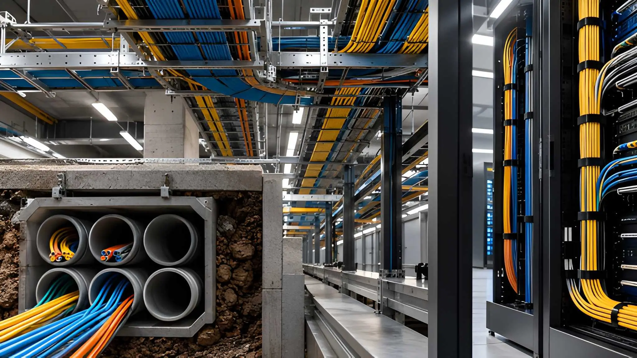
An AI campus may have room for additional computing equipment, available electrical capacity, and cooling infrastructure capable of supporting further deployment, yet still encounter connectivity constraints when existing pathways cannot accommodate a planned cable installation. The obstruction may sit above a rack, behind a cabinet, beneath a service road, or inside a conduit that appeared adequate during the original design. Engineers often encounter these restrictions only when a new network fabric, additional optical links, or a revised equipment layout requires routes that the existing installation cannot accommodate. At that stage, the problem extends beyond the amount of cable that can physically fit inside a pathway. It concerns whether technicians can install, protect, identify, maintain, and replace that cable without compromising the routes already in service. The resulting constraint can affect deployment sequencing even when the site’s principal electrical and thermal systems retain usable capacity.

As an AI campus develops through successive construction phases, equipment refreshes, and network architecture changes, engineers must assess whether existing pathways can accommodate new connections without compromising installation access or future maintenance. An initial installation establishes routes around structural elements, electrical distribution, cooling equipment, fire protection, and the spaces required for inspection and repair. Later projects must work within that physical arrangement, even when their connectivity requirements differ from the assumptions that shaped the original design. A pathway that once supported straightforward installation can become difficult to use after additional cables occupy its accessible sections and competing services restrict the remaining approach routes. Understanding the available space consequently requires more than measuring the empty area inside individual components. It requires examining the entire route from its point of origin to its final equipment connection, including the transitions that determine whether nominally available space remains usable.
Redefining Campus Capacity: Physical Pathway as a Binding Constraint
For this article, physical pathway capacity describes the ability of a site’s containment infrastructure to accommodate planned connectivity throughout its intended service life, subject to the applicable installation requirements. The assessment includes cable trays, ladder racks, conduits, duct banks, handholes, vertical managers, overhead drops, and cabinet entry points. Each component contributes to the route, but no component operates independently of the geometry surrounding it. A spacious tray cannot compensate for a congested conduit that feeds it, while an open conduit cannot overcome a cabinet entry that leaves insufficient room for safe cable placement. Engineers must therefore evaluate capacity as a connected route rather than as an inventory of separate containment components. This approach makes pathway availability a measurable engineering condition instead of a subjective judgment based on visual inspection.
The route must also accommodate the physical characteristics of the cables that will occupy it. Cable diameter, construction, bend radius, pulling tension, support requirements, and installation method influence whether a pathway can accept an additional run without damaging existing connections or restricting future maintenance. A conduit with apparently unused internal space may still impose an unacceptable installation path when bends, transitions, or intermediate access points complicate cable placement. Overhead systems introduce different constraints because support arrangements, crossing services, structural obstructions, and working clearances determine how installers can reach the intended route. Rack-side pathways add another layer of complexity when cables must descend, turn, pass through openings, and enter cabinets without violating their mechanical requirements. A credible capacity assessment must account for these conditions before it treats any remaining physical space as available for future connectivity.

Capacity must account for future installation and continued access
The difference between physical occupancy and usable capacity becomes especially important as a site evolves. Existing cables may occupy only part of a tray’s nominal area, yet their arrangement can leave little room for additional runs that require separation, orderly routing, or access to connections beneath the existing bundle. A proposed cable may fit when considered alone but become impractical once engineers account for the space needed to introduce it through a transition or remove it during a later replacement. Maintenance access also matters because a pathway that permits initial installation can become difficult to service after adjacent systems occupy the surrounding space. Engineers should assess whether the proposed route supports the complete installation task, not merely whether its cross-section appears large enough. That assessment establishes a more defensible basis for deciding whether existing containment can support a planned network expansion.
A route-based assessment offers a proposed method for documenting capacity decisions by identifying the segments that constrain a planned connection and explaining why those segments govern its installation. Rather than recording only tray dimensions or conduit occupancy, engineers can identify the sections that constrain a proposed connection and explain why those sections govern the route’s remaining capability. A site may retain considerable open space across most of its network pathway while a single transition prevents another cable group from reaching its destination. That transition becomes the controlling constraint because the complete connection depends on every segment remaining usable. Documentation should therefore connect the physical condition of each segment with the installation requirements of the intended cable system. Such records help distinguish a genuine capacity shortage from a routing problem that an alternative path could resolve without rebuilding existing infrastructure.
Operational Fill vs Rated Fill: Defining True Limits in Tray Systems
A pathway can satisfy its applicable installation requirements and still offer limited capacity for future connectivity. Rated fill describes a permitted condition under a defined set of rules, while operational fill describes how effectively a live installation uses the available space. Engineers should not treat these measures as interchangeable because they answer different questions. Compliance checks whether an installation meets the requirements that apply to its particular wiring method, cable type, and jurisdiction. An operational assessment asks whether another cable group can traverse the route, enter the required equipment, and remain accessible for future work. The second assessment must account for the actual arrangement of installed cables, the geometry of the route, and the demands of the proposed installation.
Operational assessment begins by examining the physical arrangement rather than relying exclusively on the total area occupied by cable. A tray may contain a large amount of unused cross-sectional space, yet cable groups can obstruct the intended placement of a new run when they occupy the most accessible part of the tray. Existing support arrangements, dividers, cable separation requirements, and the approach to vertical transitions can further limit the usable route. The assessment must also consider whether an installer can introduce a cable without moving or damaging operational connections. In this context, unused area and usable installation space represent different engineering conditions. Recording both prevents a nominally available tray from receiving an unjustified capacity rating.
Measuring usable space through route conditions
A useful operational assessment divides the tray route into segments that reflect meaningful changes in its physical arrangement. Straight runs, bends, junctions, vertical transitions, and equipment approaches may each impose different restrictions on cable placement. Engineers can record the dimensions of each segment, the existing cable arrangement, the applicable installation requirements, and the amount of space available for the intended addition. They should then verify whether the proposed cable can pass through the complete sequence of segments without violating its installation requirements. This method identifies the section that controls the route instead of allowing an open section to conceal a downstream restriction. It also gives the design team a repeatable basis for comparing alternative routes when the original pathway approaches exhaustion.
Operational fill should ultimately describe the space that a proposed installation can use under the conditions that actually govern the route. The calculation must account for the cable package, the containment geometry, the permitted installation method, and any separation or access requirements that apply. Rather than assume a universal reserve percentage, engineers should establish a justified allowance for each pathway configuration based on its geometry, intended cable installation, maintenance requirements, and documented future demand. A straight tray run may retain useful expansion room even when another segment requires immediate intervention, while a densely occupied junction may become restrictive despite a modest overall fill level. The result should identify both the available capacity and the physical condition that limits further use. That approach turns tray assessment into a practical planning tool for future network changes.
Duct Bank Saturation: How Underground Congestion Blocks Future Fiber Routes
Underground pathways often appear easier to expand than overhead systems because their conduits remain concealed beneath roads, paved areas, and service corridors. That appearance can conceal a difficult constraint: engineers must establish a continuous route through buried infrastructure that offers limited visibility after construction. A duct bank may contain available conduits near a building while its approach to a handhole, building entry, or intermediate chamber prevents the proposed route from proceeding. Existing bends, duct transitions, occupied entries, and the arrangement of neighboring services can further restrict the usable path. A route assessment must therefore examine the complete underground connection rather than count empty conduits at a single location. The relevant capacity belongs to the continuous route between its endpoints, not simply to the number of ducts recorded on a drawing.
Underground capacity depends on continuity and access
The condition of handholes and intermediate access chambers also influences whether a route remains usable. Engineers need to consider the available entry space, the arrangement of existing cable loops, the approach angle of incoming ducts, and the working room needed to perform installation tasks. A conduit may remain open while its entry position makes it difficult to introduce another cable without interfering with existing runs. Access conditions can also complicate inspection, identification, and future replacement when several routes converge within a restricted chamber. These constraints may not appear in a simple conduit schedule, particularly when the schedule records duct occupancy without documenting the geometry of each transition. A reliable underground assessment should therefore include chamber conditions and entry arrangements as part of the pathway’s effective capacity.
Microduct systems introduce an additional planning consideration because their usable capacity depends on duct availability, route continuity, termination arrangements, and compatibility with the intended cable and installation method. Engineers must assess the available microducts, their continuity, their termination arrangements, and the compatibility of the intended cable with the selected pathway. An apparently available microduct cannot support a new connection if its route terminates before the required destination or if a transition prevents the intended installation method. A potential allocation problem arises when separate projects reserve the same nominally available pathway without a shared record of those commitments, making the recorded spare capacity unreliable for subsequent planning. The physical route may remain empty today even though the organization has already assigned its capacity to planned connections. Recording committed capacity alongside installed occupancy helps prevent future projects from treating reserved pathways as unallocated space.
Locating the underground segment that governs expansion
Underground pathway assessment should follow the intended route through every duct section, chamber, transition, and building entry. Engineers can document each segment’s condition, the cables it contains, its accessible space, and any restrictions that affect a proposed installation. They should also record whether a pathway has a confirmed destination and whether its route information matches the installed condition. These checks help reveal discrepancies between design records and the physical infrastructure, which can otherwise undermine expansion planning. Where drawings cannot establish the actual condition, inspection or other suitable verification may be necessary before the team assigns additional capacity. The resulting record provides a defensible view of which routes remain available and which require intervention before further deployment.
A congested handhole can govern the capacity of several routes even when the surrounding duct bank retains open conduits. When multiple ducts approach the same chamber, their entry positions and the arrangement of existing cables determine how effectively installers can access individual pathways. A new connection may require a different approach angle, additional working room, or a route through a chamber that already contains tightly arranged cable loops. Engineers should therefore identify shared access points and evaluate how proposed additions would affect other routes that depend on them. Reviewing shared access points helps engineers identify whether a proposed change could move a restriction to another connection that depends on the same chamber or duct entry. It also clarifies when an additional chamber, revised duct alignment, or separate entry route may offer a more durable solution than adding more ducts to an already restricted approach.
Overhead Pathway Saturation: Tray Stacking, Crossover and Intersection Load
Overhead pathways provide visible access to connectivity infrastructure, but their apparent openness can obscure the restrictions created by junctions and changes in direction. A straight tray may accommodate its existing cable groups without difficulty while a nearby crossover forces several routes through the same restricted space. Ladder intersections, drops, vertical transitions, and hall-to-hall connections can also reduce the room available for orderly cable placement. Engineers who assess only the longest straight sections may consequently overestimate the capacity of the complete overhead system. The limiting point often appears where separate routes converge or where the containment must change direction to reach another part of the site. A route-based assessment must therefore examine these transitions with the same care applied to the tray runs themselves.
Why straight tray capacity can misrepresent the complete route
Tray stacking introduces additional constraints because the available space depends on the complete arrangement of the overhead services. Engineers must account for the intended tray configuration, the support structure, access for installation, and the requirements that govern nearby electrical and mechanical services. Adding another tray layer may appear to provide additional containment, but the proposed arrangement must still fit within the available structural and service envelope. It must also preserve access to existing cables and avoid creating difficult transitions at intersections and equipment approaches. A design that adds linear tray capacity without examining these conditions may shift congestion from a straight run to the next junction. The assessment should therefore consider how each proposed tray addition changes the route as a whole.
Intersections deserve separate attention because they combine geometric restrictions with competing installation requirements. Cables approaching from different directions may need to turn, cross, or separate before reaching their destinations, leaving less practical room than the individual tray dimensions suggest. Existing cable bundles can also make it difficult to introduce new routes without disturbing established connections. Engineers should inspect these locations for bend constraints, crossing arrangements, support limitations, and the working space needed to carry out installation and maintenance. Where several routes share a single transition, the team should document which connections depend on it and how future additions could affect them. This information makes it possible to identify a local bottleneck before it restricts an entire network expansion.
Crossover planning and inter-hall connectivity
Inter-hall routes often combine long overhead runs with a series of transitions that determine whether a new connection can reach its destination. The route may pass through structural openings, corridor crossings, shared service areas, and changes in elevation before entering the receiving space. Each transition introduces a physical condition that the installation team must evaluate, including the available clearance and the geometry required by the cable. An open tray at the starting point cannot compensate for an inaccessible crossover farther along the route. Engineers should therefore trace proposed inter-hall connections through their complete paths and document the conditions at each transition. This provides a more reliable picture of usable capacity than a drawing that records only the nominal size and length of the tray sections.
The arrangement of overhead services can also affect the sequence in which technicians can install or replace cables. A proposed route may have sufficient physical space but require work in a location where neighboring services obstruct access or prevent the intended installation method. Changes to one tray may affect nearby routes when they share supports, intersections, or restricted transitions, so engineers should evaluate those dependencies before modifying the existing arrangement. Engineers should document these dependencies before assigning additional cable capacity to the affected sections. They should also determine whether an alternative path would reduce congestion without introducing new problems at the destination. The purpose is to establish a route that remains installable and serviceable as the site changes, rather than merely adding containment wherever the ceiling appears open.
Rack-Side Ingress Constraints: Vertical Pathways and Cabinet Entry as Final Bottleneck
A campus route does not become usable simply because a cable reaches the correct room or overhead tray. The final approach must deliver the cable through the vertical pathway, into the cabinet area, and to the intended connection point without violating the applicable installation requirements. Vertical managers, overhead drops, cabinet openings, and internal routing arrangements can all restrict that final movement. A tray may retain open space above a rack while the available cabinet entry cannot accommodate the proposed cable arrangement. The problem can become more difficult when existing bundles occupy the most direct approach or when the intended route requires a bend that the entry geometry cannot support. Engineers must therefore treat rack ingress as a separate capacity layer within the complete connectivity route.
Why a clear overhead route can end at a restricted rack
Cabinet entry also affects how technicians organize, identify, and service the cables after installation. A cable that enters through a restricted opening may leave little room for orderly routing to the intended port or panel. Existing connections can obstruct access to new routes, while crowded vertical managers can make it harder to follow an individual cable through the cabinet. The assessment must consider the complete path from the overhead drop to the final termination rather than stop at the cabinet boundary. Engineers should verify that the proposed arrangement allows the cable to reach its destination while preserving the access required for future work. This review helps reveal rack-side constraints before the network team schedules a connection that the physical installation cannot support.
Rack-side congestion can also emerge from changes to equipment layouts and connection patterns. A cabinet that originally supported a straightforward cable approach may later require additional fabrics, revised port arrangements, or connections to equipment in a different position. Those changes can alter the preferred entry route even when the cabinet’s external dimensions remain unchanged. Engineers should examine the proposed connection against the current equipment arrangement and any planned changes that affect the route. They should also verify whether existing cable bundles can accommodate the intended addition without creating an installation or maintenance problem. A rack-side assessment that reflects the actual equipment layout provides a more reliable capacity decision than a generic allowance based only on cabinet size.
Treating ingress as a measurable capacity layer
A rack-side assessment should document the vertical route, entry opening, internal manager, and destination connection as connected parts of the installation. Engineers can record the available space, existing cable arrangement, applicable bend requirements, and restrictions that affect access to each section. They should then confirm that the proposed cable can traverse the route without relying on an assumption that the installer will find a workaround on site. Where the cabinet lacks a usable entry path, the team should identify whether an alternative opening, revised cable approach, or separate vertical route can resolve the restriction. The assessment should capture the reason for the limitation and the evidence supporting the proposed solution. This creates a consistent basis for comparing rack-side capacity across different equipment layouts.
The rack-side review should connect each cabinet’s ingress conditions to the upstream pathway that supplies it. An available vertical manager has limited value if the overhead drop cannot reach it, while a clear drop cannot support a new connection if the cabinet entry remains blocked. Engineers should record these dependencies so that teams can identify the true controlling segment before changing the route. They should also maintain an accurate record of cable destinations and reserved entries, especially when several equipment changes compete for the same approach. This information supports better coordination between network design, physical installation, and equipment deployment. It also ensures that campus capacity assessments reflect the final connection point rather than stopping at the room or tray level.
A Framework for Quantifying Pathway Exhaustion Across Campus Layers
A unified pathway assessment needs a common method for describing the physical capacity that remains available across underground, overhead, and rack-side systems. The method should begin with a route inventory that identifies each segment, its location, its containment type, and the connections that depend on it. Engineers should document installed occupancy, relevant installation requirements, physical access, and any known restrictions that affect future cable placement. They should also distinguish verified spare capacity from space that a project has reserved or that remains unverified. These records create a shared basis for evaluating different pathway types without pretending that every tray, conduit, and cabinet follows the same calculation. The resulting model can compare conditions across the site while preserving the engineering details that determine whether each route remains usable.
Establishing a consistent route-level assessment
The assessment should evaluate every route as a sequence of connected segments, including transitions and destination entries. For each segment, the team should establish whether the intended cable can pass through the available space under the applicable installation conditions. The model should record any restriction caused by geometry, existing occupancy, access, or a lack of verified route information. Engineers can then identify the segment that governs the proposed connection and determine whether another route could support the same requirement. This approach avoids assigning a capacity value to an entire route based on its most spacious section. It also makes the assessment useful for project planning because it identifies where intervention would have the greatest effect on the intended connection.
A practical model should keep physical capacity separate from planned demand. Installed cables occupy space, while approved future connections may reserve additional capacity even before installation begins. Engineers should record both categories so that a route does not appear available merely because the planned cable has not yet arrived. The model should also identify assumptions that remain unresolved, such as uncertain conduit destinations or unverified cabinet entries. Those assumptions should remain visible until inspection or design verification resolves them. By keeping occupancy, reservations, and uncertainty separate, the assessment can show which parts of the route network genuinely support additional connectivity.
Building a usable capacity score without hiding the bottleneck
A site-wide assessment can use a simple classification to communicate pathway condition, provided the classification does not replace the underlying engineering record. For example, engineers can label a segment as available, constrained, exhausted, or unverified according to documented installation conditions. An available segment supports the intended addition, while a constrained segment requires a defined intervention or an alternative route. An exhausted segment cannot support the proposed installation under its current configuration, and an unverified segment lacks enough evidence to justify a capacity decision. These labels should apply to a specific proposed cable package or connection requirement, not to every possible future installation. The classification gives decision-makers a clear overview while retaining the technical explanation behind each result.
The controlling condition for a complete route should reflect its most restrictive required segment. If an underground duct, overhead intersection, or cabinet entry cannot support the intended cable, open space elsewhere does not make that route available. Engineers can express this principle through a route-level capacity measure that uses the least capable segment as the governing constraint. However, the measure should not imply that every pathway type shares a common physical unit or that a single percentage can represent all installation conditions. The model must preserve the reasons behind the restriction, including cable geometry, access, reservations, and applicable requirements. A unified assessment should standardize the decision process rather than erase the differences between underground ducts, overhead containment, and rack-side routing.
Engineering for Preserved Space in High-Density Campus Design
Pathway capacity becomes a governing infrastructure constraint when a site can no longer establish a usable route for the next required connection. The restriction may arise in an underground duct, at an overhead intersection, or at the final entry into a cabinet. Each location presents a different physical problem, but all can prevent a planned connection from reaching its destination. Engineers therefore need to assess connectivity pathways as complete installation routes rather than as isolated components with nominal spare space. That assessment must consider physical occupancy, installation requirements, access, reserved capacity, and the condition of each transition. Treating those factors as part of capacity planning gives the site a more reliable basis for evaluating future network expansion.
Preserving the expansion room requires design teams to record not only what they install but also what the remaining pathway can realistically support. A tray with unused area does not guarantee that a new cable can negotiate its intersections, and an empty conduit does not guarantee a continuous route through the underground system. Likewise, an open overhead drop cannot establish usable capacity if the cabinet entry remains restricted. Engineers should document these conditions during design, verify them during installation, and update them when equipment layouts or network requirements change. The resulting record can identify approaching constraints before a proposed expansion depends on a route that no longer supports the required installation. This process makes the physical pathway a continuing part of infrastructure planning rather than an afterthought once the available space has disappeared.









