
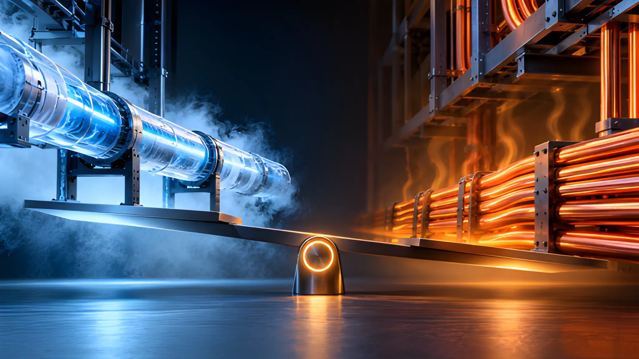
A power distribution system can become more expensive to operate as current, routing constraints, and conductor losses increase, although the point at which an alternative technology becomes economically preferable depends on the complete installed system. In a high-density AI environment, the problem may begin with the copper conductors carrying power between distribution equipment and the rack-level power infrastructure, where rising current, restricted routing space, and concentrated electrical demand turn an apparently routine connection into a consequential engineering decision. Replacing conventional conductors with high-temperature superconducting technology changes the physical arrangement, but it also introduces a cooling system whose energy consumption, maintenance requirements, and operating dependencies become part of the distribution equation. The comparison therefore extends beyond conductor resistance and into the machinery required to preserve superconductivity throughout normal operation and under abnormal conditions.

The answer depends on the location of the proposed installation, the electrical duty it must support, the route between its endpoints, and the way the surrounding infrastructure operates throughout its service life. A short connection serving a variable workload may offer little opportunity to recover the cost of cryogenic equipment, even when its peak current appears demanding. A longer, continuously loaded trunk serving concentrated demand presents a different calculation because conductor losses persist during operation, while the value of compact power delivery may extend beyond energy savings to include pathway capacity and reduced installation complexity. Neither condition automatically favors superconductivity, since the cryogenic plant introduces fixed and variable costs that conventional copper distribution does not require. A sound comparison must evaluate both alternatives against the same delivered-power requirement, operating profile, redundancy obligation, maintenance strategy, and financial assumptions.
Why the PDU-to-RDU Layer Defines the Loss Equation
The connection between power distribution and rack-level distribution occupies a position where the electrical design must translate the output of upstream equipment into a form that the computing environment can use. Its conductors carry the aggregate demand of downstream loads, so their current depends on the delivered power, operating voltage, electrical arrangement, and actual workload. Copper losses arise from conductor resistance, and their magnitude changes as current and conductor temperature change under operating conditions. Designers cannot assess these losses reliably by examining the conductor material alone because conductor geometry, parallel paths, joint resistance, installation conditions, and loading patterns also influence the result. A route that looks electrically adequate on a single-line diagram may impose a different thermal and installation burden once engineers account for actual cable placement, termination arrangements, and neighboring services.
The Electrical Boundary Between Distribution and Rack Demand
A facility-wide efficiency measure can conceal the local behavior of this connection because it combines electrical distribution with conversion losses, cooling consumption, auxiliary equipment, and other loads that do not necessarily change when a conductor technology changes. An improvement in an upstream transformer or a reduction in cooling demand can alter the overall efficiency result without changing the losses in the PDU-to-RDU path. Conversely, a distribution segment can become a significant source of avoidable energy consumption even when the wider system continues to perform within its expected operating range. Engineers should isolate the relevant path, establish its delivered electrical load, and calculate losses under representative operating conditions before comparing alternatives. They should also identify which upstream and downstream losses remain common to both designs, because including unchanged loads in the comparison can dilute the apparent benefit of the proposed conductor.

The comparison should include the installation footprint, service access, and supporting equipment required by each arrangement, because the relative space and maintenance requirements depend on the selected conductor and cryogenic system designs. Copper feeders require conductor space, supporting structures, termination access, and routing provisions that suit their electrical and thermal characteristics, while a superconducting system requires a cryostat, thermal insulation, coolant circulation where applicable, refrigeration equipment, controls, and service access. The physical footprint of the conductors alone therefore cannot establish which design uses less valuable space after installation. Engineers must compare the complete routes and their supporting equipment, including the positions needed for maintenance, isolation, and fault response. The assessment should also separate the cost of the conductor from the cost of the electrical and mechanical infrastructure that makes it usable.
Establishing a Comparable Delivered-Power Model
A meaningful lifecycle comparison starts with the same electrical duty for both technologies rather than comparing a superconducting conductor at its design limit with a copper system operating under a different load assumption. Engineers should define the required delivered power, operating voltage, power factor where relevant, load variation, route geometry, environmental conditions, and expected service life before estimating energy consumption. The copper case should reflect the actual conductor arrangement, including parallel runs, joints, support systems, and the electrical resistance expected at operating temperature. The superconducting case should include conductor losses that remain under the selected operating conditions, heat entering the cryogenic envelope, termination heat loads, coolant circulation requirements, and refrigeration electricity. Both cases must also include conversion losses and auxiliary loads that differ between the proposed configurations, while keeping common loads outside the incremental comparison.
A further requirement is to separate direct energy savings from the value of physical capacity that a compact conductor arrangement might release. If conventional feeders consume a large share of a constrained route, an alternative that reduces conductor volume may help the site accommodate additional electrical infrastructure without expanding the existing pathway. That benefit has economic value only when the released space addresses a documented constraint or avoids a credible cost, rather than when the model assigns an arbitrary premium to compactness. Engineers should establish whether the alternative changes support requirements, access clearances, installation sequencing, or the amount of pathway infrastructure needed to serve the load. They should then evaluate those effects alongside the cost of cryogenic equipment and the operational resources required to maintain it.
The Limit of Parallel Feeders in High-Density Distribution
Parallel copper feeders provide a familiar way to increase current-carrying capacity without relying on a single oversized conductor. The arrangement divides the electrical load across multiple paths, subject to the requirements for conductor sizing, protective coordination, termination design, and current sharing. It can support staged deployment and use established installation practices, but each additional feeder also occupies physical space and adds connections that engineers must install, inspect, and maintain. As routing becomes more congested, the design must account for the complete bundle rather than assuming that every conductor can operate under its isolated ampacity rating. Cable spacing, ambient conditions, grouping, support geometry, and the availability of ventilation can influence the thermal conditions around the installed conductors. The result is a design problem in which adding copper can solve an electrical capacity constraint while making pathway management, installation access, and heat removal more difficult.
Why Adding Copper Changes the Physical Problem
The electrical losses also require careful treatment because current sharing does not remove resistive loss from the system. For a conductor with a given resistance, resistive heating rises with the square of current, while the resistance itself changes with conductor material and temperature. Dividing a load across parallel paths can reduce the current carried by each path, but the total loss depends on the resistance and geometry of all conductors together. Engineers must therefore calculate the installed arrangement instead of assuming that the addition of feeders either eliminates the loss problem or necessarily worsens it. Connection quality matters because uneven resistance at terminations can affect current distribution and create localized heating, while differences in route length or conductor characteristics can complicate current sharing. A credible comparison uses the actual conductor schedule and installation layout to determine the losses of the complete copper system under the expected operating profile.
Pathway capacity creates a separate constraint that electrical calculations alone cannot resolve. Additional feeders need support, bending space, termination room, identification, separation where required, and access for safe inspection or replacement. When the site already has tightly coordinated overhead services, the available route may become the limiting resource before the electrical rating of the distribution equipment reaches its design boundary. A proposed feeder arrangement can also interfere with future expansion if it consumes space reserved for additional power, cooling, monitoring, or other essential services. The project team should model the physical arrangement with the same care used for the electrical single-line diagram, including realistic installation tolerances and maintenance access. Only then can it determine whether a compact superconducting trunk would solve a real routing problem or whether a revised copper layout could deliver the required capacity at a lower lifecycle cost.
When Pathway Constraints Begin to Affect Lifecycle Economics
Parallel feeders become a potential economic constraint when their combined installation, operating, and pathway requirements increase the cost of delivering the required capacity, although whether an HTS alternative reduces total lifecycle cost must be established through a project-specific comparison. Copper remains a well-understood option, with familiar procurement channels, established termination practices, and maintenance procedures that operators can incorporate into existing work processes. A superconducting alternative must compete against that complete operating environment, not simply against the price of the copper metal it replaces. Its economic case strengthens when a constrained route makes additional feeders difficult to accommodate or when the required current creates substantial avoidable electrical losses over the planned operating life. However, the presence of a congested pathway does not establish that superconductivity will win, because the cryostat, refrigeration system, control equipment, and redundancy provisions also occupy space and create service requirements.
Utilization determines whether the cost of solving the pathway problem can be recovered through sustained operation. A route carrying a variable load may spend substantial time below its peak design condition, reducing the energy savings available from lower conductor losses while leaving the capital and maintenance requirements of the selected architecture largely intact. A consistently loaded trunk presents a different profile because its electrical losses persist across a larger share of operating hours, although the cryogenic plant also consumes energy whenever it must maintain the conductor within its operating temperature range. The model should therefore apply the same time-based load profile to both designs and account for periods of reduced demand, planned maintenance, and operating conditions that affect cooling performance. A high peak current alone cannot establish an economic break-even point when the conductor spends much of its service life carrying a lighter load.
Deconstructing Cryogenic Overhead Beyond Refrigeration
A high-temperature superconducting cable does not operate as an ordinary conductor with an unusually low electrical resistance, because its operating condition depends on maintaining the superconducting material within a controlled thermal environment. The cable assembly must limit heat transfer from the surrounding environment while accommodating heat entering through electrical terminations, mechanical interfaces, and other parts of the installation. Its thermal envelope includes the conductor, electrical insulation, cryostat, coolant passages where applicable, and the interfaces connecting the cold assembly to equipment operating at ambient temperature. Heat can enter through solid materials, residual gas within an insulation space, radiation across surfaces, and the ends of the cable where thermal and electrical functions intersect. The resulting heat load determines the cooling capacity that the refrigeration system must continuously provide under the specified operating conditions.
Thermal Ingress and the Real Cost of Maintaining Superconductivity
Thermal ingress begins with the physical design of the cable and its installation, which means that the route and termination arrangement can influence refrigeration demand before the system carries its intended electrical load. Insulation performance depends on the complete cryostat construction, the condition of its vacuum or insulating medium where used, the quality of thermal breaks, and the integrity of interfaces exposed to ambient conditions. Mechanical supports and penetrations can create additional heat-transfer paths if the design does not control their thermal conductance. Terminations also require particular attention because they must connect a cold conductor to conventional electrical equipment without allowing unnecessary heat to flow into the cryogenic region. Engineers should assess these interfaces as part of the installed route rather than treating the cable’s thermal performance as an intrinsic property that remains unchanged after deployment.
The refrigeration system converts the thermal load into an electrical overhead that belongs in the same operating-cost calculation as copper’s resistive losses. The relationship depends on the refrigeration cycle, operating temperature, cooling capacity, heat-exchanger performance, coolant circulation requirements, and the operating point at which the equipment must run. Refrigeration equipment consumes electricity to remove heat at a temperature substantially below the surrounding environment, so the electrical work required cannot be inferred directly from the thermal load alone. Pumping and circulation equipment may add further consumption, while controls and auxiliary components can introduce additional loads that vary with the system configuration. A model should therefore use documented performance for the selected cooling architecture and distinguish measured equipment performance from ideal thermodynamic calculations. The resulting estimate should reflect the complete cooling system under realistic operating conditions, rather than assigning a generic refrigeration penalty to every superconducting cable design.
From Thermal Load to Dependable Operating Cost
The cryogenic overhead includes more than the electricity consumed by refrigeration during stable operation, because the system must also manage startup, shutdown, temperature recovery, and changing thermal conditions. A cooling system may operate differently during initial cooldown than it does after the cable reaches its normal operating temperature, and maintenance activities can alter the thermal state of the installation. The design must establish how the cable behaves when the cooling plant changes operating mode, when a component requires service, or when an interruption affects the circulation system. Engineers should examine the thermal capacity of the complete assembly and the operating procedures that preserve its condition during disturbances. They should also identify the conditions under which the conductor can continue to operate safely and the conditions that require load reduction or electrical isolation.
Maintenance planning should reflect the architecture of the refrigeration system rather than assume that all cooling equipment requires the same intervention strategy. A design using multiple cooling units may allow individual components to receive service while the remaining equipment supports the required thermal load, provided that the installed capacity and control logic support that operating mode. A configuration with less redundancy may require a planned interruption or a temporary change in electrical loading when its cooling equipment becomes unavailable. The cost model should capture routine inspection, component servicing, spare-parts availability, specialist labor, and the operational consequences of scheduled maintenance. It should also consider how the design allows operators to identify degrading performance before the system reaches a condition that threatens superconductivity. These provisions determine whether the cooling architecture remains manageable over the intended service life or creates recurring costs that erode the conductor’s electrical savings.
Current, Distance and Utilization: The Three Variables That Shift Break-Even
Electrical current influences the economic comparison because resistive losses in conventional conductors increase with the square of current when resistance remains constant. That relationship makes high-current distribution an important candidate for closer evaluation, but it does not establish a universal threshold at which a superconducting cable becomes cheaper. The copper system’s resistance depends on conductor material, cross-sectional area, operating temperature, geometry, and the arrangement of parallel paths used to carry the load. Increasing conductor size can reduce resistance, although the resulting installation may require more material, support capacity, termination space, and pathway area. A superconducting conductor changes these physical tradeoffs, but the complete system still incurs thermal and electrical overhead associated with maintaining and operating the cryogenic assembly. The relevant calculation compares the losses of the actual copper design with the combined electrical and cooling consumption of the proposed superconducting design at the same delivered load.
Current Determines the Scale of Avoidable Conductor Loss
The model should distinguish the current that the distribution system encounters during normal operation from the current that it must accommodate under a specified contingency or future expansion scenario. A design sized for a demanding peak may operate below that condition for much of its life, which changes the energy savings available from reduced conductor resistance. Engineers should also confirm the electrical conditions at the PDU and RDU boundaries, including the voltage and phase arrangement, because the same delivered power can produce different current requirements under different distribution designs. The copper baseline should reflect realistic conductor sizing and installation conditions rather than an artificially constrained alternative that exaggerates the value of superconductivity. The superconducting design should likewise account for its specified operating envelope, including the thermal and electrical conditions that limit dependable current carrying.
High current can increase the potential value of a compact distribution path when site drawings and installation assessments demonstrate that additional conventional feeders would require costly pathway modifications or constrain other essential infrastructure. The economic benefit may include avoided pathway modifications, simplified routing, or the ability to preserve space for other essential infrastructure, provided that the design demonstrates those outcomes. Such benefits should remain separate from energy savings so that the financial model does not count the same physical advantage twice. The project team should compare the installed footprint of the copper feeders, their supports and terminations, and the full superconducting assembly with its cryogenic equipment and service access. It should then determine whether the proposed design reduces an actual site constraint or merely shifts the congestion from the electrical route to the cooling system.
Distance and Utilization Determine How Quickly Savings Accumulate
Routing distance changes the comparison because the resistance of a conventional conductor generally increases with its length, while a longer superconducting route can increase the thermal burden associated with the cable assembly. A longer copper route can therefore accumulate additional resistive losses, but a longer cryogenic route may require more insulation, greater coolant-flow capacity, additional thermal management, or a different refrigeration arrangement. The relative effect depends on the conductor design, installation geometry, thermal performance, and operating conditions rather than distance alone. Engineers should use the actual site route, including bends, vertical transitions, penetrations, and termination locations, instead of relying on a simplified straight-line measurement. They should also determine whether the proposed cryogenic system requires intermediate equipment or other design changes to maintain acceptable thermal and hydraulic performance along the route. The break-even model must compare the electrical and thermal behavior of both complete routes under consistent assumptions.
The model should evaluate these variables together because current, distance, and utilization do not produce independent economic effects. A long route carrying high current under sustained operation may accumulate substantial copper losses, while a short route carrying a variable load may offer limited energy savings despite a demanding peak. A longer superconducting route may also increase the cost and complexity of the cryogenic system, changing the result even when its conductor offers favorable electrical performance. Engineers should test the interaction between route length, expected loading, conductor sizing, thermal ingress, and refrigeration efficiency rather than changing one assumption while leaving all other assumptions fixed. The analysis should identify which variables have the greatest influence on the result and which uncertainties require additional measurement or supplier validation.
Redundancy as a Design Input, Not an Afterthought
A superconducting distribution system depends on a cooling arrangement that can preserve the required operating temperature throughout the conditions defined by its electrical design. Its reliability assessment must therefore consider the refrigeration plant, coolant circulation, temperature monitoring, controls, auxiliary power, and the interfaces connecting these elements to the electrical distribution system. A failure in one component does not necessarily produce an immediate loss of electrical function, because the response depends on the thermal capacity of the cable assembly, the operating state of the cooling equipment, and the protection strategy. Engineers must establish how the system behaves when a refrigerator stops, circulation becomes unavailable, or a control component produces an unexpected operating condition. The assessment should also define the conditions that trigger an alarm, require load reduction, or demand isolation of the affected electrical path.
Cooling Availability Changes the Economics of the Electrical Path
Cooling redundancy introduces additional capital and operating requirements, but its economic effect depends on the architecture rather than the mere presence of backup equipment. A system with independently serviceable refrigeration units may preserve cooling availability during certain component failures, provided that the remaining capacity can support the actual thermal load. An arrangement with a shared coolant circuit, common controls, or a common auxiliary power source may retain dependencies that limit the protection offered by duplicated equipment. The design review should therefore examine the complete failure path, including the components that remain common to nominally redundant subsystems. Engineers should document which failures the architecture can tolerate, which failures require an electrical operating change, and which conditions could force a planned interruption. The cost model should reflect the redundancy actually required to meet the operating objective instead of assigning a generic premium to every superconducting installation.
The electrical comparison must also consider the consequences of cooling unavailability rather than counting only the electricity consumed during normal operation. A cooling interruption can create operational costs if it requires load transfer, workload rescheduling, temporary derating, or an outage of the affected distribution path. Those costs depend on the thermal behavior of the cable, the available alternate supply, the duration of the interruption, and the operating procedures established for the site. Copper distribution also requires redundancy, protection, and maintenance planning, so the comparison should use equivalent service requirements for both alternatives. Engineers should assess whether the existing electrical topology can accommodate the superconducting system’s operating dependencies without introducing a new common point of failure. The resulting model connects reliability requirements to financial consequences and prevents the conductor’s electrical characteristics from dominating a decision that depends on the entire installed system.
Quench Recovery and Dual-Path Operation
A quench occurs when a region of a superconducting conductor loses its superconducting state and develops resistance, changing the electrical and thermal behavior of the affected section. The response depends on the conductor design, operating current, protection system, and the conditions that initiated the event. Engineers must understand how the system detects an abnormal condition, limits the resulting electrical and thermal stress, and determines whether the affected path can return to service. Recovery may require inspection, stabilization of the thermal system, restoration of the required operating conditions, or replacement of damaged components, depending on the event. The lifecycle model should account for the resources and time associated with recovery rather than assuming that every interruption ends when the cooling system resumes normal operation. This assessment helps establish whether the proposed superconducting arrangement can satisfy the site’s availability requirements under credible failure scenarios.
A dual-path design adds another layer to the assessment because each path must remain compatible with the electrical and thermal requirements of the overall distribution topology. If both paths use superconducting conductors, the design must establish how each cryogenic subsystem behaves during normal operation, maintenance, and a fault affecting the other path. If the system combines superconducting and conventional conductors, engineers must assess the interfaces, transfer arrangements, and operating restrictions associated with the different technologies. The presence of two physical routes does not automatically establish independence when they share controls, cooling equipment, electrical protection, or other components whose failure can affect both paths. The reliability model should identify these shared dependencies and explain how the system responds when an individual component or supporting service becomes unavailable. Those findings determine whether the installed redundancy meets the intended operating requirement and whether its cost is justified by the resilience it delivers.
Defining the Handoff Point in a Hybrid Distribution Topology
A hybrid distribution topology can be evaluated by assigning superconducting conductors to segments where modeled electrical losses and documented physical constraints may justify their additional costs, while retaining conventional conductors on segments where the complete lifecycle comparison does not support extending the cryogenic system. The approach recognizes that the route between upstream distribution equipment and the rack contains segments with different current levels, distances, installation constraints, and maintenance requirements. A high-current trunk may carry an aggregated load across a constrained route, while the final connection to rack-level equipment may serve a smaller load over a shorter distance. These segments create different opportunities to recover the cost of superconducting equipment through reduced electrical losses and improved use of available pathway space. The optimal arrangement therefore depends on the actual electrical duty and physical conditions of each segment rather than a preference for one conductor technology across the entire installation.
Assigning Superconductivity to the Trunk Rather Than Every Connection
The handoff point should be identified by comparing the incremental cost and performance of extending the superconducting section against those of retaining conventional conductors downstream, including electrical losses, thermal overhead, installation, maintenance, and reliability requirements. Engineers should evaluate the combined cost of conductor losses, thermal ingress, refrigeration consumption, installation, terminations, maintenance, and redundancy along the proposed route. Extending superconductivity closer to the rack may reduce the length of conventional conductors, but it can also add cryogenic interfaces, increase the thermal burden, and complicate access to equipment that requires regular service. Ending the superconducting section earlier may simplify the cryogenic system while increasing copper losses or requiring additional downstream conductors. The design process should compare candidate handoff locations against the same electrical load and operating profile, using the installed configuration rather than theoretical conductor performance alone.
A topology-aware evaluation can make this decision more transparent by comparing each candidate segment against consistent technical and financial criteria, provided the method identifies its assumptions and does not present an unvalidated scoring system as an established industry standard. The model should record the electrical load, route length, expected utilization, copper losses, cryogenic heat load, equipment requirements, maintenance implications, and effect on pathway capacity for every alternative. It should also account for the interfaces between technologies, because a hybrid design introduces connections and protection requirements that may differ from those of an entirely conventional arrangement. The scoring process should not assign arbitrary weights that conceal the underlying tradeoffs or combine unrelated benefits into a single unexplained value. Instead, the project team should show how each criterion contributes to lifecycle cost, reliability, or a documented site constraint.
Testing the Hybrid Design Against the Complete Site Requirement
A hybrid topology must preserve the electrical coordination of the complete path, including the interfaces between superconducting trunks, conventional busway or cable feeders, and rack distribution equipment. Engineers should examine voltage performance, fault-current behavior, protection coordination, grounding, termination requirements, and the consequences of switching between available supply paths. The design should also account for the physical arrangement of cryogenic equipment and conventional electrical infrastructure so that the transition does not create an inaccessible maintenance area or an unnecessary concentration of critical components. Thermal management remains important near the handoff because the superconducting section must preserve its operating conditions while the conventional section must manage its own electrical and thermal requirements. The interface design should therefore follow the requirements of both technologies rather than treating the transition as a simple change in conductor material.
The site design should retain enough flexibility to accommodate changes in computing demand without assuming that the initial distribution arrangement will remain optimal throughout its service life. Future rack configurations, workload changes, electrical equipment replacement, and revised redundancy requirements can alter the current profile and the relative value of each distribution segment. A hybrid arrangement may offer a manageable transition between technologies, but only when engineers define how the system can expand, isolate, inspect, and maintain each section. The design should document the conditions that would justify extending superconductivity farther downstream or replacing a conventional segment with a different distribution arrangement. It should also establish the measurements and operating records needed to validate the original assumptions after commissioning. This creates a technical basis for future decisions and reduces the risk that the selected handoff point becomes an inflexible constraint as the site’s electrical requirements evolve.
Where Superconductivity Delivers System-Level Advantage
The economic case for high-temperature superconducting distribution emerges when the complete installed system delivers a better lifecycle result than a technically credible conventional alternative. Low conductor resistance is an important input, but it cannot establish that result independently of the cooling system, electrical interfaces, installation requirements, and reliability provisions. The comparison must begin with the actual power distribution path between the PDU and RDU, because that boundary identifies the conductor losses and physical constraints the proposed technology can change. Engineers should then evaluate the effects of current, route length, utilization, thermal ingress, refrigeration efficiency, and maintenance requirements under consistent operating assumptions. The financial model must also include the costs of redundancy and recovery so that the superconducting system meets the same service requirements as the copper alternative. These elements establish whether the proposed architecture offers a measurable advantage at the site rather than merely an attractive electrical characteristic in isolation.
A Lifecycle Decision Grounded in Operating Conditions
A favorable result requires more than a demanding peak load, because the expected savings depend on how often the system operates under conditions that create substantial copper losses. A short route with variable demand may leave too little energy savings to compensate for refrigeration and maintenance costs, even when its conductor sizing appears challenging. A sustained high-current trunk with a constrained pathway may offer a stronger opportunity, particularly when the superconducting arrangement also avoids credible installation or expansion costs. That opportunity still depends on the thermal design, because a longer cryogenic route or a cooling system with substantial fixed overhead can change the result. Engineers should test the design under realistic load profiles and sensitivity cases rather than treating a single calculation as a permanent answer.
Evaluating a handoff point allows engineers to test whether superconductivity offers sufficient value on a high-current trunk to justify its additional costs while retaining conventional conductors on downstream segments where the lifecycle analysis does not support extending the cryogenic system. A superconducting trunk can be evaluated for the route where high current, sustained utilization, and pathway constraints create the strongest economic opportunity, while conventional conductors can continue to serve shorter connections where cryogenic overhead offers less value. The design must still demonstrate that its interfaces, protection arrangements, cooling dependencies, and maintenance procedures satisfy the site’s operating requirements. A complete lifecycle model can then compare copper-only, hybrid, and superconducting alternatives while preserving a clear link between engineering assumptions and financial outcomes. The selected architecture should follow from the evidence gathered for the specific site, with explicit recognition of the conditions that could alter its economics.
Turning the Break-Even Model Into a Design Decision
Commissioning and operational measurement should validate the conditions that underpin the original comparison. The installed system’s electrical loading, conductor temperatures, refrigeration consumption, cooling stability, and maintenance behavior can reveal whether the model reflects actual operation. Engineers should compare measured performance with the design assumptions and investigate material differences before using the results to justify further deployment. The same process should apply to copper distribution, where measured loading, temperature, voltage performance, and observed maintenance needs can improve the conventional baseline. A consistent measurement approach helps the site refine its lifecycle model as operating conditions change and as more reliable information becomes available. It also creates a stronger basis for deciding whether superconducting distribution should remain limited to the original trunk or extend into additional segments.
Superconductivity delivers a system-level advantage when its reduction in conductor losses and its physical benefits outweigh the complete cost of maintaining the technology under the site’s actual operating conditions. Copper and busway remain valid alternatives where their installation, utilization, and maintenance characteristics produce a lower lifecycle cost or where cryogenic dependencies create an unacceptable operating burden. The strongest design process evaluates both options against the same electrical requirement, tests the assumptions that govern their performance, and identifies the conditions that would reverse the result. It also recognizes that a hybrid arrangement can place superconductivity where its value is strongest while preserving conventional distribution for connections that do not justify the additional complexity. The final decision belongs to the complete distribution architecture, including its cooling equipment, electrical interfaces, pathway requirements, and redundancy provisions. A defensible break-even result therefore emerges from operational evidence and site-specific engineering rather than from conductor resistance alone.









