
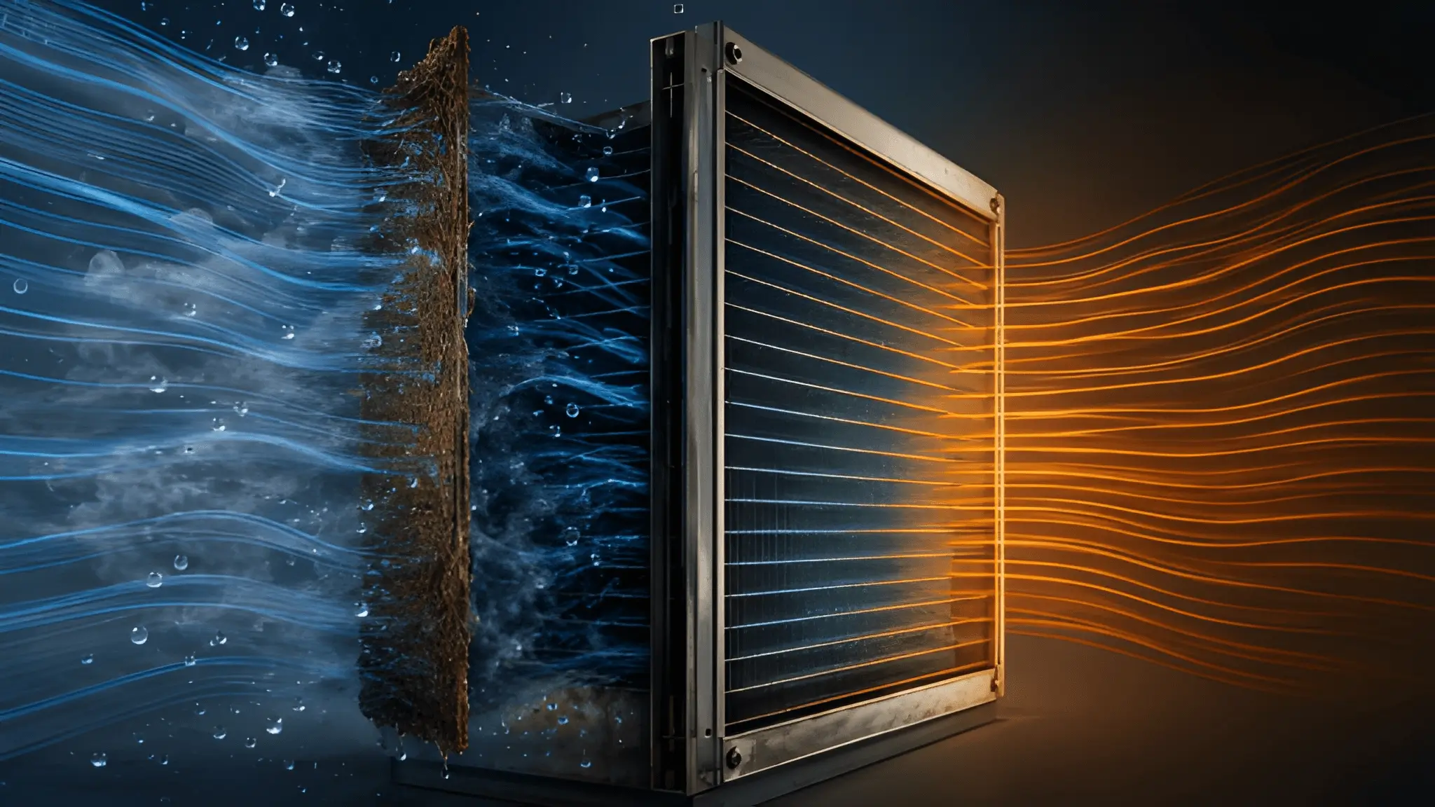
A condenser coil can carry the correct nameplate capacity and still experience operating conditions that its original aerodynamic design never anticipated. The problem begins when an upstream evaporative pad, screen, barrier, or other obstruction changes how air approaches the coil face rather than simply reducing the total airflow rate. Once that happens, the fan continues to move air, but the coil no longer sees the spatially consistent velocity field assumed during selection. High-velocity paths can develop beside regions where air movement becomes weak, creating a face that behaves differently from one section to another. Moisture also responds to those local conditions, because evaporation, droplet transport, surface wetting, and drying depend on the velocity and thermodynamic state of the air reaching each portion of the coil.

The important distinction is between total airflow and airflow distribution, because those two quantities can diverge when an obstruction sits immediately upstream of a heat-transfer surface. A fan may deliver nearly the expected volumetric flow while the pressure field forces that flow through preferred openings and leaves other portions of the face comparatively starved. Such redistribution changes local Reynolds number, convective heat transfer, moisture removal, and the ability of a surface to dry after exposure. A wet region with weak airflow can therefore remain wet longer than a neighboring region receiving stronger flow, even when both regions share the same ambient conditions. Corrosion does not respond to the average airflow reported by a controller; it responds to the local combination of surface condition, contaminant concentration, temperature, moisture, and exposure time.
Condenser Faces Are Engineered for Uniform Velocity, Not Obstructed Intake
Coil geometry starts with an aerodynamic assumption that air will approach the available face in a reasonably predictable manner. Fin spacing, tube arrangement, coil depth, and face area collectively determine resistance, while the selected fan and system pressure budget establish the airflow available across that geometry. Closely spaced fins create more air-side resistance, and additional rows or extended surfaces increase that resistance further, so the design point represents a relationship between geometry and pressure rather than a simple airflow number. When an evaporative pad covers part of the intake face or sits immediately against it, that relationship changes because the coil receives an inlet pressure field different from the one used during selection. A covered region may experience reduced momentum while an adjacent opening becomes an easier route for the same fan-driven flow, producing spatial differences that the total cubic-feet-per-minute reading cannot reveal.
Fin geometry also determines how readily moisture leaves the coil surface, which makes uniform approach conditions important beyond heat-transfer performance alone. A coil with tightly controlled fin spacing expects a particular balance between air resistance, surface wetting, and moisture transport, while the same coil can behave differently when upstream structures create local acceleration and stagnation. Condensate can move differently across neighboring regions when pressure and velocity vary, and weak-flow pockets can retain surface moisture instead of exchanging it rapidly with the surrounding airstream. Uneven airflow across a coil face can also indicate upstream stratification, particularly when several air paths converge or when an obstruction changes the resistance immediately before the coil. The design question is not simply whether the pad cools the incoming air, but whether the resulting air field still satisfies the coil’s aerodynamic and moisture-management requirements.
Pressure Drop Across Pad Media and the Velocity Distortion It Creates
Evaporative media introduces its own pressure loss, and that loss depends on media geometry, thickness, airflow velocity, and operating condition. Published technical data for rigid evaporative media show that pressure loss increases as air velocity rises and that pad depth also affects resistance, making the media a meaningful component of the system pressure budget. A uniform pad can produce a predictable pressure drop when its water distribution and physical condition remain consistent, but real installations can develop local differences caused by fouling, mineral accumulation, uneven wetting, damaged media, or installation gaps. Air naturally seeks paths offering lower resistance, so sections with lower upstream resistance can receive more flow while adjacent regions experience weaker momentum. The result is not necessarily a dramatic reduction in total airflow, but rather a redistribution of airflow that changes the operating environment seen by different portions of the condenser.
Wet media also changes the thermodynamic condition of the air before it reaches the heat-transfer surface, which adds another layer to the aerodynamic problem. Evaporation removes sensible heat from the airstream while increasing its moisture content, and the extent of that process depends on media depth, velocity, water distribution, and operating conditions. High-resistance sections can suppress local flow, while neighboring paths carry a disproportionate share of the air and may leave the media under a different evaporation regime. Meanwhile, water distribution across the pad can also develop dry or overloaded regions, and technical guidance recognizes that inadequate water distribution can create dry areas and reduce evaporative performance. A condenser positioned immediately downstream has little physical distance in which these differences can dissipate, so the coil inherits much of the non-uniformity created upstream.

Non-Uniform Airflow, Non-Uniform Corrosion
Corrosion becomes more complicated when moisture and contaminants encounter a surface that does not dry consistently. Aluminum fin surfaces normally rely on a protective oxide layer, but that protection can become less effective when environmental chemistry and persistent surface moisture create conditions favorable to localized attack. Chloride ions are particularly important because they can concentrate as water evaporates and can weaken protective surface films, increasing susceptibility to pitting under suitable chemical conditions. A low-velocity pocket does not automatically produce corrosion, but it can increase the residence time of moisture and dissolved contaminants at the surface, changing the exposure history compared with a better-ventilated region. Repeated wetting and partial drying can also leave concentrated deposits behind, meaning that the chemical environment on one section of a coil may differ materially from another section exposed to the same incoming air.
Localized pitting or fin deterioration should consequently be interpreted alongside airflow distribution rather than viewed only as a materials-selection problem. Laboratory research on aluminum has demonstrated that chloride deposition and atmospheric moisture can influence corrosion behavior, with the surface electrolyte becoming an important part of the corrosion process. A stagnant or weakly ventilated region can provide more opportunity for a surface moisture film to persist, while repeated evaporation can concentrate soluble contaminants that remain after the bulk water disappears. Edge regions can also experience unusual flow behavior because the pressure field changes near physical boundaries, gaps, and transitions between obstructed and unobstructed areas. The combination can create localized exposure conditions that an average environmental assessment may not fully capture, particularly where moisture and chloride-containing deposits remain concentrated at the surface.
Separation Distance as a Thermal Design Parameter
Distance between a wetted evaporative source and a condenser face provides physical space for the airstream to redistribute before it encounters the coil. That space does not eliminate pressure loss or guarantee perfect uniformity, but it can provide additional distance for jets, wakes, and localized velocity gradients to redistribute before reaching a surface that depends on predictable airflow. The same separation can also support more complete evaporation, reducing the likelihood that liquid droplets or highly localized wet regions reach the condenser intake. A properly configured arrangement gives designers an opportunity to evaluate the combined system as an air-handling path rather than treating the pad and coil as independent components. Inspection access also improves when the evaporative media does not occupy the same physical envelope as the condenser face, allowing technicians to examine fin condition, fouling, moisture evidence, and physical damage.
Thermal design should account for the complete path from the evaporative source to the condenser because temperature and humidity are only part of the resulting inlet condition. Mixing length, velocity recovery, droplet behavior, access requirements, and pressure losses all influence whether the downstream coil receives the environment assumed during design. A physical gap can also make maintenance more effective because operators can inspect the media and coil separately instead of working through a compressed interface where fouling and moisture conditions are difficult to observe. Water management matters at the same time, since technical guidance emphasizes preventing uncontrolled moisture carryover and maintaining conditions that allow surfaces and drainage areas to remain properly managed. Specification should consequently define the intended relationship between the evaporative equipment and condenser rather than relying solely on the pad manufacturer’s performance data or the condenser’s nameplate rating.
Airflow History Defines Long-Term Coil Integrity
A condenser coil can accumulate the effects of operating conditions through changes that may not appear in first-year performance data. Uneven airflow can alter local heat transfer, moisture residence, contaminant deposition, and drying behavior without necessarily producing an immediate alarm at the system level. Over repeated operating cycles, those local differences can contribute to variations in moisture exposure and contaminant deposition, while corrosion susceptibility remains dependent on the material, surface condition, moisture, chlorides, and other environmental factors. The same principle applies to maintenance because a coil that appears acceptable from a distance may contain concentrated deterioration in areas that repeatedly experience poor airflow or persistent moisture. Nameplate performance remains important, but it describes a defined operating envelope rather than every condition that an installed coil may encounter after upstream modifications.
Long-term coil integrity therefore depends on treating airflow as a spatial design variable rather than a single number displayed by a fan controller. Measurements such as face velocity mapping, differential pressure, temperature distribution, humidity, and visual inspection can reveal conditions that average system readings conceal, particularly after evaporative equipment is installed or modified. A design that keeps the condenser face unobstructed, provides adequate distance for upstream airflow to redistribute, controls liquid carryover, and preserves inspection access creates a more controlled operating environment. This approach does not promise that corrosion will disappear, because material selection and environmental exposure remain fundamental variables, but it reduces the likelihood that an avoidable airflow distortion becomes an additional degradation mechanism. The engineering lesson is straightforward: protecting the coil requires preserving the conditions under which its aerodynamic, thermal, moisture, and materials assumptions remain valid throughout its service life.











