
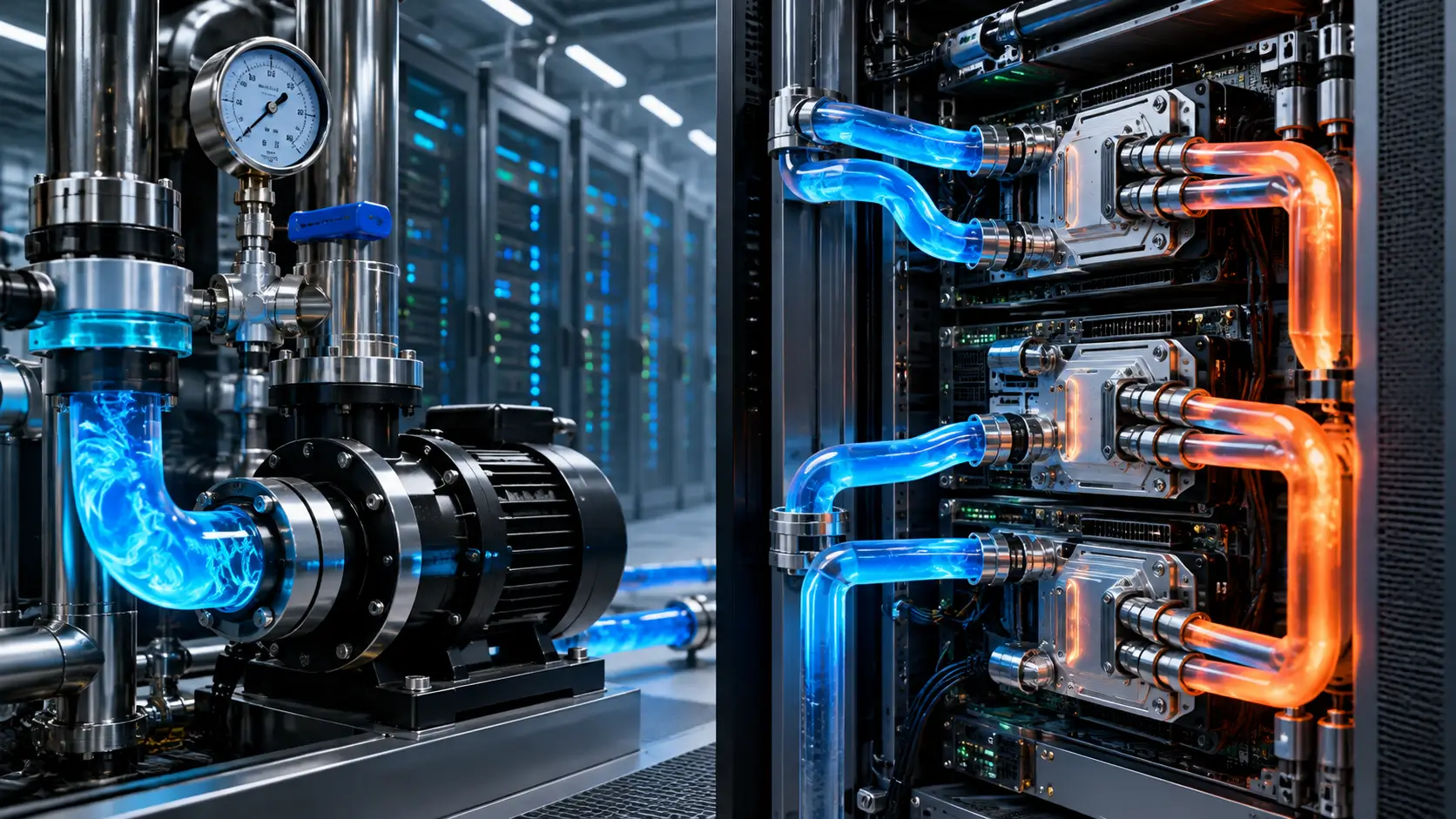
AI capacity can look available on paper while a less visible constraint develops underneath the servers. Power may remain available. Rack positions may also remain open. Network capacity may have room for another deployment. Yet the cooling network serving that location can have little hydraulic margin left. For liquid-cooled AI infrastructure, that difference changes what “available capacity” actually means. Coolant must move through a physical network before it can carry processor heat away. That network includes pumps, pipes, valves, manifolds, hoses, connectors, and cold plates. Each component affects how the coolant moves. Restrictions create pressure loss along the route. Different branches can also receive different amounts of coolant. As a result, installed cooling capability does not always equal cooling deliverable to every compute position.

Liters per minute offer a useful way to examine this hidden layer. However, flow cannot work as a standalone capacity score. Temperature, pressure, coolant properties, thermal load, and hydraulic resistance also matter. The hardware configuration changes the relationship between those variables. A meaningful capacity assessment must therefore examine the entire thermal-hydraulic path. That path ultimately determines whether available infrastructure can support another compute deployment.
AI Capacity Is Becoming Partly a Hydraulic Problem
Power remains one of the clearest constraints in AI infrastructure planning. Every server needs an electrical path capable of supporting its operating load. Liquid cooling adds another infrastructure chain beside that electrical system. Coolant must reach the processors and carry their heat away. That movement depends on the hydraulic network serving the rack. Electrical availability alone cannot confirm that this second chain supports the planned hardware. Coolant travels through several components before it reaches a processor cold plate. Headers, manifolds, valves, hoses, and connectors all influence that journey. Each element introduces some hydraulic resistance. The pump must overcome that resistance to maintain the required circulation. A change in one part can alter conditions elsewhere. Cooling capacity therefore depends partly on the complete path between distribution equipment and computing hardware.
This matters because a powered rack still needs continuous heat removal. Direct liquid cooling brings coolant close to high-heat components. The fluid circuit therefore becomes part of the server’s thermal operating environment. Different server paths can present different hydraulic characteristics. Their flow may change with resistance and pressure conditions. Operators must consequently evaluate cooling delivery as well as electrical delivery before treating capacity as deployable.

Hardware changes can alter the cooling requirement
Compute infrastructure changes faster than much of the mechanical system around it. Pipes and manifolds may support several generations of servers. Pumps and distribution equipment can also remain while processors change. A replacement server may fit inside the same physical rack. It may connect to the existing electrical system without difficulty. Yet its thermal-hydraulic characteristics can differ from the hardware it replaces. Cold plates are one source of that difference. Internal channels influence both heat transfer and pressure loss. Hoses and connectors can also change between server designs. Even internal plumbing can affect the resistance presented to the wider cooling network. These differences do not automatically create a problem. They do mean that cooling compatibility should be checked instead of assumed.
This distinction becomes important during refresh planning. A new compute generation does not enter an empty mechanical environment. It inherits the pipes, pumps, manifolds, and distribution topology already in place. Those systems were often selected around earlier hardware assumptions. The next server design may still operate within that envelope. However, planners need evidence before treating that compatibility as guaranteed.
Flow Can Reveal Locally Stranded Cooling Capability
Cooling capacity can exist upstream without being fully usable at every rack. The reason is straightforward. Heat can only leave a processor if the cooling path can transport it. A heat exchanger may retain operating margin. The distribution path serving one rack can still become restrictive. This creates a local capacity problem rather than a site-wide cooling shortage. Hydraulic resistance helps explain how that can happen. Coolant loses pressure as it travels through pipes and components. Valves, connectors, hoses, and cold plates contribute to that resistance. Branch geometry also affects the resulting flow distribution. A restrictive path can therefore receive different flow from another branch. Aggregate cooling capability does not remove these local differences.
For planners, the distinction is similar to electrical distribution. Available upstream power does not prove that every downstream circuit can accept another load. Cooling requires the same location-aware thinking. The relevant question is whether coolant can reach the intended hardware under validated conditions. That makes cooling capacity partly a distribution problem. It also explains why system-wide totals can hide rack-level constraints.
More flow is not automatically better
Liters per minute should not become a target that operators simply maximize. Higher flow can improve heat transfer under some operating conditions. It also increases pressure loss through many cooling components. Pumps then need to provide additional hydraulic effort. The thermal benefit may also become smaller as operating conditions change. More coolant movement therefore does not automatically mean more useful compute capacity. The objective is to deliver the flow required by the thermal design. Pressure must remain inside the supported operating envelope. Temperature conditions must also stay suitable for the hardware. Components need to operate within their validated limits. Controls must keep the network stable as loads change. Capacity depends on satisfying these conditions together.
This makes hydraulic headroom more nuanced than spare pump output. A pump may have unused capability while another component approaches its limit. A branch may also become restrictive before the central cooling system does. The reverse can occur in another design. Planners therefore need to identify the narrowest point in the complete cooling chain. Liters per minute help reveal that point when interpreted with pressure and temperature.
Flow Connects Compute Demand to Heat Transport
Coolant flow becomes useful when paired with the heat entering the liquid. Temperature change is central to that relationship. Coolant absorbs heat while moving through the server cooling path. Its thermal properties also affect how much heat that movement can transport. The same volumetric flow can therefore support different thermal conditions. Flow alone cannot describe the resulting cooling capability. This is why liters per minute cannot serve as a universal conversion from rack power. Different coolants have different physical properties. Different cold plates also transfer heat differently. Inlet temperature changes the thermal conditions at the component. Server geometry can alter both resistance and heat transfer. Capacity calculations need to preserve these relationships rather than reducing them to one number.
The practical value of flow comes from context. Operators can compare flow with supply and return temperatures. They can also examine pressure conditions across relevant portions of the network. Together, these measurements describe the cooling state more clearly. They help distinguish distribution problems from other thermal limitations. That makes flow useful as evidence rather than as an isolated capacity rating.
Cooling equipment and cooling delivery are different concepts
A major cooling component can retain headroom while another part becomes restrictive. Consider a heat exchanger with available thermal capability. The downstream network may still need validation for another server configuration. Pumping conditions can also limit what reaches the rack. In another system, the distribution network may remain capable while heat exchange becomes tighter. No single equipment rating can describe every case. Capacity planning therefore needs to follow the complete heat path. Heat begins at the processor. It moves through the cold plate into the coolant. The coolant then travels through server and rack distribution. Additional infrastructure transfers that heat farther through the cooling system. Every stage must support the intended operating condition.
This changes the meaning of cooling capacity for decision-makers. Installed equipment describes what exists. Deliverable cooling describes what can support a specific compute configuration. The two values can align closely in a well-matched deployment. They should not be assumed to be identical. That distinction becomes more important as AI hardware changes within long-lived mechanical infrastructure.
The Cooling Path Matters as Much as the Source
A liquid-cooled rack receives coolant through a physical route. Supply piping feeds distribution branches. Those branches connect with rack manifolds. Manifolds divide flow among server cooling paths. The coolant then passes through components that collect heat. It eventually returns through the cooling network. Every transition affects hydraulic behavior. Pipes create friction. Fittings introduce additional resistance. Valves influence both control and pressure loss. Connectors allow serviceability but also affect the flow path. Cold plates present their own hydraulic characteristics. The resulting system behaves as a connected network rather than a collection of independent components.
This network behavior makes location important. Two racks can appear identical from a floor-planning perspective. Their cooling conditions may still differ. Each can occupy a different point in the distribution topology. Their neighboring loads may also differ. Available hydraulic margin can consequently vary across the same data hall.
Pump operation does not prove downstream flow
A running pump confirms that mechanical equipment is operating. It does not prove that every downstream branch receives the required coolant. Flow depends on the pump and the network together. Changes in resistance alter the system operating point. Valve positions can influence distribution. Component condition can also affect hydraulic behavior. Server changes add another variable. A replacement cooling loop may present different resistance from the previous design. That difference can alter flow through parallel paths. The pump itself may remain unchanged. Yet the coolant distribution experienced by servers can shift. Monitoring pump status alone would not capture that change.
Measurements closer to compute can provide better visibility. Rack-level flow can show how much coolant reaches a local distribution point. Differential pressure can add hydraulic context. Temperature measurements show the thermal result. These signals become stronger when analyzed together. They help operators understand whether upstream cooling capability actually reaches the hardware.
Rack Manifolds Can Define the Local Capacity Boundary
A rack manifold divides coolant among several server paths. Those paths may not have identical resistance. As a result, coolant does not necessarily divide evenly among them. Experimental work has observed flow maldistribution inside direct liquid-cooled rack systems. This finding matters for capacity planning. Total rack flow cannot independently prove suitable coolant delivery to every server. Processors experience local cooling conditions rather than rack averages. One branch can behave differently from another. Hardware configuration can amplify those differences. Valves and flow-control elements can help manage distribution. However, those components also become part of the hydraulic network. Their behavior must remain inside the design assumptions.
For capacity planners, the key question sits below the rack total. Each active server path must receive suitable coolant conditions. The network must maintain those conditions under the intended operating configuration. Another server can change the shared hydraulic environment. That makes rack capacity partly dependent on distribution behavior. It also makes manifold design important for future flexibility.
Mixed hardware can complicate distribution
Hardware refreshes rarely require every server to change at the same moment. Older and newer systems can coexist during a transition. Their cooling loops may present different hydraulic characteristics. One server design can use different connectors or internal passages. Another may use a different cold-plate architecture. A common manifold then has to support both configurations. This does not make mixed deployments inherently problematic. Properly engineered systems can accommodate different paths. However, operators need to validate the resulting distribution. Equal flow should not be assumed where hardware requirements differ. The correct condition depends on each server’s thermal design. Capacity therefore needs to follow the actual connected hardware.
This also affects lifecycle planning. A manifold installed today may remain through later compute generations. Its adaptability becomes part of the rack’s future value. Generous hydraulic flexibility can support a wider range of configurations. A tighter design may require mechanical changes sooner. Buyers should therefore treat manifold capability as part of long-term cooling readiness.
Server Plumbing Consumes Hydraulic Margin
Cold plates receive considerable attention because they sit close to high-heat processors. Yet coolant passes through other components before reaching them. It also passes through components after collecting heat. Hoses, connectors, fittings, valves, and internal tubing all affect the route. Experimental rack research has shown that server plumbing can contribute materially to pressure loss. The complete cooling path therefore matters. This finding changes how hydraulic margin should be assessed. A high-performing cold plate can still sit behind restrictive plumbing. Pumping requirements depend on the assembled loop. Looking only at cold-plate performance can miss resistance elsewhere. Capacity calculations should therefore include installed server-side components. Simplified assumptions can otherwise overstate available margin.
The principle becomes more important during hardware replacement. A new server may change several small components at once. Individually, those changes may appear minor. Together, they can alter the pressure-flow relationship of the branch. The wider cooling network then sees a different hydraulic load. That is why server plumbing belongs in upgrade validation.
Serviceability components still need hydraulic accounting
Quick-disconnect connections provide clear operational value. They allow technicians to service liquid-cooled hardware more easily. Hoses also make installation and replacement practical. Valves provide isolation and control. These components should not be viewed as undesirable restrictions. Their hydraulic effects simply need to be included in the design. A cooling network has a finite operating envelope. Different components consume portions of the available pressure differential. Designers account for those losses when selecting pumps and distribution equipment. They also need margin for expected operating variation. Future hardware can use some of that remaining flexibility. Once margin becomes tight, further changes may require mechanical work.
This resembles infrastructure capacity accounting. Every path has conditions it must satisfy. Additional resistance can reduce flexibility somewhere else. Greater pump output is not always the appropriate answer. Downstream components still have pressure and flow limits. Understanding the complete hydraulic budget is therefore more valuable than focusing on one component.
Cooling Distribution Can Become a Compute Boundary
Cooling distribution equipment links broader cooling infrastructure with server-side loops. Its role includes heat transfer and coolant circulation. A headline thermal rating captures only part of that job. The system must also deliver suitable flow and pressure downstream. Pump behavior influences that ability. Network resistance and controls matter as well. Several racks can share the same distribution system. Each rack adds another hydraulic path. Activating or changing a branch alters the connected network. Control systems can compensate within their designed range. They cannot create unlimited hydraulic capability. Eventually, a component or path can become the limiting condition.
This is why expansion planning needs more than a thermal rating. Planners need to understand the proposed topology. They also need the expected server characteristics. Operating states matter too. A cooling system can support its current deployment while requiring changes for another configuration. That does not mean the existing design has failed.
Cooling headroom should reflect realistic operating conditions
Capacity looks different under ideal and realistic conditions. A hydraulic model with minimal resistance can overstate practical flexibility. Real systems contain valves, connectors, fittings, filters, and control elements. Their states can change over time. Maintenance can also alter the available path. Capacity analysis should account for the operating conditions that actually matter. This becomes especially important when cooling supports critical compute. A deployment may need to continue through defined maintenance states. The surviving cooling path must then support the intended load. If it cannot, operators need another operating strategy. That could include changing compute load or cooling configuration. The correct response depends on the design.
For buyers, the important issue is transparency around usable headroom. Current operation does not automatically prove future flexibility. Successful commissioning validates a particular configuration and tested conditions. Another hardware generation may need another assessment. Cooling headroom should therefore represent validated margin. It should not simply mean unused nameplate capability.
Pump Headroom Can Become Deployment Headroom
Pumps create the pressure difference that moves coolant. Their operating point depends on the connected hydraulic network. Adding or changing equipment can shift that operating point. The pump does not work independently of system resistance. This relationship matters during expansion. Another compute configuration can therefore change the pumping conditions required. Present operation offers useful information but does not answer every future question. A pump may operate comfortably with current hardware. That does not prove compatibility with another server design. New branches can change the network. Different cold plates can also change resistance. Planners need to evaluate the proposed state rather than extrapolating from the current one.
This makes pump margin part of deployment planning. However, pump margin alone still does not define cooling capacity. Heat exchangers, pipes, manifolds, and server loops can become limiting first. The whole system must remain within its operating envelope. A larger pump cannot erase every downstream restriction. Capacity therefore emerges from the connected system.
Resilience changes the available hydraulic picture
Installed pumping capability can differ from capability available during maintenance. The same applies during a component outage. A system may normally have several pumping resources available. A changed state can leave fewer hydraulic paths. Flow distribution can then differ from normal operation. Capacity planning needs to recognize those conditions when they matter to service commitments. This does not require every design to maintain full load through every possible event. Resilience targets differ. Workload priorities also differ. Cost and architecture influence the appropriate approach. What matters is defining the states that the service intends to support. Cooling behavior should then be validated against those states.
The distinction is similar to electrical resilience planning. Installed equipment and resilient capacity answer different questions. Liquid cooling needs the same discipline. Normal-state flow cannot automatically represent degraded-state capability. A service promise should rely on cooling conditions that remain available during the relevant operating state. That makes hydraulic resilience a capacity issue rather than only a mechanical issue.
Aggregate Flow Can Hide Local Constraints
An upstream flow meter provides valuable information. It shows coolant movement through that point in the system. However, it cannot independently describe every downstream branch. Parallel paths can receive different flows. Resistance and control settings influence that distribution. Local measurements therefore answer questions that upstream totals cannot. The cooling network contains several useful observation levels. Distribution equipment provides one view. Rack manifolds provide another. Server loops can provide more granular information. Each measurement answers a different operational question. Together, they create a clearer picture of cooling delivery.
This layered approach becomes valuable during expansion. Upstream equipment can retain headroom while one branch approaches its limit. Another branch may still support additional hardware. A system-wide total could hide both conditions. Topology-aware measurements reveal where capacity remains usable. That improves rack selection and upgrade planning.
Local cooling limits are not always site limits
A restrictive branch does not automatically mean the entire site lacks cooling capacity. The limitation can be local. Another distribution path may have more margin. Conversely, strong site-wide cooling numbers do not prove that one specific rack is ready. Capacity must be attached to location. This is one of the most important consequences of liquid cooling. The same idea already appears in other infrastructure systems. Electrical capacity follows distribution topology. Network capability also depends on paths and architecture. Cooling increasingly needs similar treatment. Heat must physically travel from the processor through the coolant network. Where that network narrows, compute capacity can narrow with it.
For C-level planning, this changes how expansion opportunities should be interpreted. An available rack is not automatically an available deployment. A local cooling check can reveal hidden work. Another location may avoid that work. Better visibility can therefore improve both schedule and capital allocation. Hydraulic information becomes useful when it guides these choices.
Workload Placement May Eventually Reflect Cooling Distribution
Schedulers generally treat compute through logical resource characteristics. Mechanical cooling operates at another layer. Yet servers can occupy locations with different infrastructure conditions. Their racks may connect to different branches. Those branches can have different hydraulic margins. Physical equivalence should therefore not always be assumed. Workload intensity also changes heat generation. Some portions of a cluster can operate harder than others. Cooling controls respond to those changing conditions. The relationship does not mean schedulers should directly operate pumps. It does suggest value in stronger visibility between compute capacity and cooling telemetry. Physical constraints should become visible before they disrupt logical allocation.
This remains an analytical direction rather than a universal industry practice. Its value lies in better infrastructure awareness. A capacity system could flag racks approaching their validated cooling envelope. Workload teams could then understand the physical dependency. Cooling controls would remain responsible for mechanical operation. The two layers would simply share better capacity information.
Cooling telemetry can support usable compute planning
A provider may own installed accelerators that depend on different physical cooling paths. Those paths can have different margins. Logical accelerator count therefore does not describe every infrastructure condition. Internal capacity systems can account for those differences. They do not need to expose raw hydraulic telemetry to customers. They only need to avoid assuming that all installed hardware is physically interchangeable. This becomes important when customers reserve sustained compute. The hardware must operate under the conditions contemplated by the service. Power, network, and cooling all contribute to that ability. A weakness in one chain can constrain the complete service. Cooling telemetry can help providers identify such dependencies early. That improves the quality of capacity planning.
Liters per minute fit naturally into this internal model. Flow shows whether coolant moves through a given path. Pressure and temperature explain the context. Hardware requirements define what conditions are acceptable. The resulting assessment can then feed a simpler capacity abstraction. Engineers retain the details while planners receive a usable answer.
Flow Headroom Is Upgrade Headroom
Compute refresh cycles and mechanical infrastructure operate on different timelines. Servers can change while pipework remains. Manifolds may also support several hardware generations. The same can apply to pumps and distribution equipment. Future compute therefore inherits many earlier infrastructure decisions. Those decisions shape the cooling envelope available later. This does not mean every new processor requires more coolant. That assumption would be too simple. Flow requirements depend on the complete thermal design. Cold-plate geometry matters. Temperature conditions and hydraulic resistance matter too. Future compatibility must therefore be assessed against actual hardware requirements.
The important planning concept is flexibility. A cooling system with greater usable margin can support more configuration options. A tightly constrained system may require changes sooner. Neither outcome can be inferred from rack power alone. Hydraulic characteristics need separate consideration. Flow headroom consequently represents one form of future compute optionality.
Mixed generations can consume that flexibility differently
Large deployments may refresh hardware gradually. Several server generations can then share cooling infrastructure. Their hydraulic requirements may differ. A common manifold must support those paths together. Flow distribution can change as equipment enters or leaves service. Operators need to validate the resulting combination. This is another reason commissioning should not be treated as a one-time event. The cooling topology evolves with the compute. New servers alter the connected network. Removed servers change it again. Valve states and branch conditions can also change. Cooling validation should therefore follow material configuration changes.
For buyers, this affects long-term infrastructure value. Flexible distribution can make later upgrades easier. Limited hydraulic margin can turn future refreshes into mechanical projects. That possibility belongs in lifecycle planning. It can affect deployment timing and capital needs. Cooling architecture therefore influences how easily compute evolves.
Cooling Retrofits Can Delay Compute Upgrades
A server upgrade appears simple when viewed only from the compute layer. Hardware arrives. Technicians install it. Power and networking get connected. Software integration follows. Liquid cooling can introduce additional dependencies before the new hardware reaches production. The replacement server may fall outside the existing cooling envelope. Branch piping could need changes. A manifold may require another configuration. Pumping or control conditions might also need adjustment. None of these outcomes is inevitable. They depend on the specific hardware and cooling architecture.
When mechanical work becomes necessary, the schedule can change significantly. Operating coolant systems require controlled intervention. Teams may need isolation plans and leak checks. Controls also need validation after changes. Downstream conditions must be confirmed before full operation resumes. Cooling readiness can therefore become part of the compute-upgrade critical path.
Modular cooling can reduce upgrade friction
Not every hydraulic modification requires broad disruption. Architecture makes a major difference. Modular distribution can isolate work more effectively. Well-placed valves can support controlled intervention. Accessible manifolds can simplify changes. Serviceable connections can also reduce maintenance complexity. These features still need hydraulic accounting. Flexibility does not eliminate pressure loss. A serviceable connector still affects the coolant path. A valve still contributes resistance. Good design balances operational flexibility with hydraulic performance. Neither goal should be considered alone.
Buyers should therefore ask how cooling expansion actually occurs. The answer matters more than a broad statement that cooling can expand. Some additional capacity may require only configuration changes. Another increment may require hardware installation. A larger change could involve distribution redesign. Those paths have different schedule implications.
Cooling Telemetry Needs to Become Capacity Telemetry
Temperature remains essential in liquid-cooled computing. It shows whether thermal conditions remain acceptable. However, temperature often reflects the outcome of several interacting variables. Inadequate flow can raise temperature. Higher compute load can do the same. Heat-transfer changes can also affect the result. Flow adds another layer of information. It shows coolant movement through a measured path. Differential pressure adds hydraulic context. Supply and return temperatures show how the thermal state changes. No single measurement explains everything. Combined measurements provide a stronger operating picture.
This matters for capacity planning as well as protection. Operators can watch whether hydraulic conditions change as compute load grows. They can identify branches that repeatedly approach their validated envelope. Such patterns can inform future deployment choices. Telemetry then becomes more than an alarm system. It becomes evidence for infrastructure headroom.
Historical behavior can expose hidden limits
Commissioning captures the system under selected test conditions. Production operation produces a wider range of states. Workloads rise and fall. Pumps and valves respond. Servers enter different utilization patterns. Maintenance can also change network configuration. Historical telemetry shows how cooling behaves through those variations. A branch may appear comfortable at average load. It may approach its boundary during sustained high utilization. Another branch might remain stable across the same period. Static capacity numbers can miss these patterns. Historical data can therefore strengthen expansion planning.
The goal is not to convert every short-term fluctuation into a capacity alarm. Operators need to separate transient behavior from recurring constraints. Trend analysis can help. So can comparison across similar operating states. Over time, cooling capacity becomes something that teams validate continuously. It no longer remains only a commissioning assumption.
Liters per Minute Need Business Context
A raw flow number can mislead when detached from its operating conditions. The same liters per minute can correspond to different thermal outcomes. Coolant properties influence heat transport. Temperature change also matters. Cold-plate characteristics alter thermal performance. Hydraulic resistance affects how the flow gets delivered. Pressure adds another important dimension. Coolant must move through real components. Those components create resistance. A theoretical flow without the required pressure conditions has little practical value. Capacity therefore needs a thermal-hydraulic context. Executives should not be asked to interpret raw pump or flow data.
Instead, engineering teams can translate those measurements into deployable cooling margin. The abstraction should preserve the physical constraint. A rack can then appear as compatible or requiring review for a proposed configuration. Engineers retain access to the underlying data. Decision-makers receive a clearer planning signal. This keeps technical rigor without overwhelming the capacity conversation.
Cooling capacity can become location-aware
A useful capacity system could connect rack availability with cooling deliverability. Power already receives this kind of treatment. Network capacity also reflects topology. Cooling should increasingly follow the same logic. A rack’s position inside the hydraulic network matters. Its available margin can differ from another rack nearby. This approach also improves refresh planning. Proposed hardware can be tested against the cooling envelope of candidate locations. One rack may support the configuration without modification. Another may require mechanical work. The compute hardware itself can be identical. The difference sits in the supporting infrastructure.
For buyers, this creates a stronger definition of ready capacity. The rack must have power. It needs network connectivity and physical space. Its cooling path must also support the intended hardware. All of those conditions need to exist together. Only then does infrastructure become deployable compute capacity.
Contracts Need a Clearer Cooling Boundary
AI capacity contracts often emphasize compute and power. Liquid cooling introduces another physical dependency. A provider can possess electrical headroom while a proposed server still needs cooling validation. The issue is not a failure of the power commitment. It is a different infrastructure condition. Contracts and technical schedules can distinguish those layers more clearly. This becomes especially relevant across hardware refreshes. The server used later may differ from the original design. Its hydraulic characteristics can change. The existing power allocation may remain suitable. Cooling compatibility may still require another review. A long-term capacity commitment should recognize that distinction.
Providers cannot reasonably guarantee compatibility with hardware that does not yet exist. They can define the cooling envelope available today. Future equipment can then be checked against it. This creates a clearer boundary for both parties. It also reduces the chance that a hardware refresh discovers an unexpected mechanical dependency late in deployment.
Ready cooling and expandable cooling are different
A site may have room to expand its cooling infrastructure. That does not make the future capacity ready today. New distribution equipment may require procurement. Pipework changes may need installation. Controls can require integration. Testing and commissioning must follow. This distinction matters for deployment schedules. Immediately usable capacity carries one lead time. Capacity requiring mechanical work carries another. Both can be valuable. They simply should not appear identical in planning systems. Buyers need to know which type they are reserving.
Liters per minute can help define that boundary when used correctly. Existing validated flow conditions describe current capability. Engineering analysis can show what another configuration requires. The gap between those states reveals whether infrastructure work is necessary. That turns an obscure mechanical issue into a clearer planning dependency. It also makes cooling expansion easier to sequence against compute procurement.
Hydraulic Resilience Differs From Installed Capacity
A cooling system can contain multiple pumps and still rely on shared hydraulic paths. Headers may be common. Manifolds can also create shared dependencies. Valves and heat exchangers influence the surviving configuration. Redundancy therefore needs to be evaluated as a complete path. Component count alone cannot establish coolant delivery. The relevant question is what happens after the system changes state. Can the remaining path support the intended compute? Are flow and pressure still suitable? Do temperature conditions remain inside the operating envelope? These questions depend on architecture. They cannot be answered from equipment quantity alone.
This distinction should match the service expectation. Some workloads may tolerate reduced compute during maintenance. Others may require a stronger continuity model. Cooling architecture should support the chosen objective. Capacity planning then needs to reflect that objective. Normal-state capability should not silently represent every resilience state.
Maintenance can change hydraulic conditions
Liquid-cooling components need maintenance like other mechanical systems. Some work requires isolation. That isolation changes the available flow path. Pressure distribution can then change. Flow through remaining branches may also change. The effect depends on the topology. Well-designed systems can localize many maintenance activities. That improves operational flexibility. Yet planners still need to understand the supported state during intervention. A rack that operates normally may face different conditions during maintenance elsewhere. The cooling model should capture those relevant scenarios. Capacity promises can then align with actual infrastructure behavior.
For C-level buyers, this is less about mechanical detail than service reliability. The provider needs to know what cooling state supports the promised compute. Buyers need clarity on the resulting capacity commitment. Raw hydraulic data can remain with engineering teams. The business layer needs a dependable interpretation. That interpretation should reflect both normal and relevant degraded conditions.
Thermal Transport Deserves Its Own Capacity Map
Capacity maps usually show where infrastructure resources remain available. Power is a common layer. Rack position is another. Network access also matters. Liquid cooling adds thermal transport to that list. A site-wide cooling number cannot always describe this resource accurately. Hydraulic capability follows physical topology. One branch can have more margin than another. Pressure losses vary across routes. Connected equipment also affects conditions. The same upstream system can therefore produce different local envelopes. Rack availability should reflect these differences.
A thermal transport map could make them visible. It would connect rack locations with validated cooling conditions. Static design information could provide the baseline. Operating telemetry could update the picture. Planners would then see where cooling supports another deployment. They could also see where engineering review is required.
The map needs to change with the infrastructure
Cooling topology is not permanently static. Servers get replaced. Branches are added or isolated. Valve positions change. Maintenance alters operating conditions. Workload patterns also shift the thermal load. A useful capacity map therefore needs updates. Flow data can show changing coolant movement. Pressure measurements can reveal hydraulic conditions. Temperature adds thermal context. Hardware configuration completes the picture. Together, these inputs describe the current cooling envelope more accurately.
Such visibility can improve infrastructure utilization. A local constraint may not require a site-wide expansion. Another branch could already have suitable margin. The map helps planners find that opportunity. It can also prevent investment in upstream cooling when the real restriction sits downstream. Better location awareness can therefore improve both capital efficiency and deployment speed.
Thermal Transport Should Join Power and Network Planning
Power does not move from source to server without intermediate constraints. Network traffic also follows physical and logical paths. Heat removal has its own topology. Processor heat enters the coolant. The coolant carries it through several infrastructure layers. Each layer can influence the final capacity. This makes thermal transport a planning resource. The resource is not merely installed cooling equipment. It is the ability to move heat from a specific compute location. Flow plays a central role in that process. Pressure and temperature determine its context. Hardware characteristics define the required operating envelope.
Capacity planning becomes stronger when these layers meet in one model. Power availability remains essential. Network topology remains essential. Cooling deliverability becomes another condition. None replaces the others. Usable compute appears where all required resources overlap.
Executives do not need fluid-dynamics dashboards
Better cooling visibility does not require senior leaders to inspect pump curves. Engineering teams can retain that detail. Capacity systems can translate it into simpler deployment information. The important point is preserving the physical constraint. Simplification should not erase it. A rack should not appear ready when cooling work remains outstanding. The same approach already works for other infrastructure domains. Executives discuss power headroom without studying every conductor. Network capacity can also be summarized without exposing every switch state. Cooling can follow a similar model. Engineers validate the operating envelope. Planning systems communicate whether the proposed deployment fits inside it.
This abstraction can improve decision speed. Procurement can identify mechanically ready locations earlier. Hardware teams can avoid configurations that require unexpected cooling work. Capital teams can see where targeted upgrades unlock usable compute. The organization then manages thermal transport as a capacity resource. Liters per minute become one of the engineering measurements supporting that decision.
Deliverable Flow Matters More Than Maximum Flow
The title of this Long Read gives liters per minute unusual prominence. That does not mean the largest flow wins. Maximum pump output does not equal usable cooling capacity. Downstream components must support the resulting pressure. Thermal conditions must also remain appropriate. Control systems need stable operation. Higher flow can improve heat transfer in some conditions. It can also increase pressure drop. Pumping demand then rises. The system may encounter another limit before the pump reaches maximum output. Therefore, the useful quantity is not maximum possible circulation. It is validated deliverable flow.
This distinction prevents a new form of capacity marketing from emerging around an incomplete metric. Providers should not compete on raw liters per minute without context. Buyers should not compare unrelated systems using that number alone. Hardware, coolant, temperature, pressure, and topology all matter. Flow only becomes meaningful inside that operating envelope.
Hydraulic efficiency preserves flexibility
Pressure loss consumes pumping capability. That makes hydraulic efficiency relevant to future capacity. Efficient design does not mean removing every restrictive component. Many restrictions serve necessary functions. Valves provide control. Connectors provide serviceability. The goal is to manage cumulative resistance intelligently. Small restrictions can repeat across many server paths. Their combined effect can become significant. Realistic modeling should include them. Installed measurements can then validate the assumptions. This produces a more reliable view of hydraulic margin.
Better efficiency can preserve flexibility for later hardware. It may reduce the pumping effort required for current loads. That does not automatically create unlimited expansion. Other constraints can still become dominant. Yet hydraulic efficiency helps more of the installed cooling system serve useful compute. It therefore deserves attention alongside thermal efficiency.
AI Readiness Requires a Validated Heat Path
A rack can have power and still lack readiness for a particular liquid-cooled server. Network connectivity does not change that fact. Physical space does not change it either. The server’s heat needs a validated path away. Coolant must reach the hardware under suitable conditions. The wider cooling system must then transport the absorbed heat. This definition makes readiness configuration-specific. An empty rack does not have one permanent cooling rating for every future server. Hardware choices alter thermal and hydraulic requirements. Distribution topology also affects available conditions. The rack and server therefore need to be evaluated together. Readiness belongs to the combined configuration.
This approach also improves deployment scheduling. Planned infrastructure should not be confused with commissioned capacity. Mechanical installation needs completion. Controls require validation. Hydraulic conditions need verification. Only then can the intended compute rely on the cooling path.
Commissioning should validate the complete operating chain
Commissioning provides the opportunity to test whether design assumptions survive installation. Pumps need to operate correctly. Distribution paths must deliver suitable coolant. Controls need to respond as expected. Server-side conditions also require verification. These checks connect the cooling design with actual compute operation. Future configuration changes can require renewed validation. A different server changes the connected system. Another rack can alter distribution. Maintenance can also change operating conditions. Commissioning should therefore be viewed as evidence for a defined configuration. It should not become a permanent guarantee for every future state.
For buyers, this creates a clearer capacity concept. Ready compute has validated supporting infrastructure. Planned compute may still depend on work. Expandable compute has another category of dependency. Separating these states makes schedules more realistic. It also makes infrastructure commitments easier to understand.
Liters per Minute Reveal a Physical Growth Boundary
The practical limit of an AI deployment appears where one required resource reaches its boundary first. In some locations, power will remain that resource. Another deployment may encounter network or physical constraints. Liquid-cooled systems can also encounter a thermal-transport limit. The narrowest resource determines what can be deployed next. That boundary can move as infrastructure changes. Flow helps identify one part of the cooling boundary. It shows coolant movement through the network. Pressure indicates the hydraulic conditions supporting that movement. Temperature connects the coolant to heat transport. Hardware requirements define whether those conditions are sufficient. Together, these variables show whether another compute configuration fits.
This does not reduce AI capacity planning to plumbing. It does the opposite. It connects mechanical infrastructure with the business outcome it supports. Compute only creates value when it can operate continuously. Heat removal is part of that operating requirement. Cooling capacity therefore deserves the same planning discipline as other critical resources.
The hidden metric is really validated coolant delivery
Liters per minute are not a replacement for megawatts. They are not a replacement for temperature either. Pressure remains important. So do coolant properties and heat-transfer design. Hardware configuration still determines the actual requirement. No single metric can replace the complete thermal-hydraulic picture. Yet flow exposes something that power-focused planning can overlook. Heat needs a transport medium. In direct liquid cooling, that medium must continuously reach the hardware. Installed cooling equipment cannot perform that task from a distance. The coolant needs a viable path through the actual network. That path needs enough operating margin for the intended configuration.
For C-level AI buyers, this changes the meaning of infrastructure capacity. Accelerators can be reserved before their complete physical dependencies are understood. Power can be secured while local cooling still needs work. Racks can exist while their thermal envelope remains unsuitable for selected hardware. A strong capacity model brings those dependencies together. It identifies what infrastructure can support compute now and what still requires modification.
The most useful question is therefore not how many liters per minute a data center can move in total. The better question asks what coolant delivery remains available at the location of the next compute deployment. That answer must include pressure, temperature, hardware requirements, and the relevant operating state. It must also account for the real distribution path between cooling infrastructure and processors. Once planners can answer that question, hydraulic headroom becomes visible before it becomes a deployment problem. The hidden capacity metric is ultimately validated coolant delivery to the compute that needs it.











