
The Grid Is Not Coming to Save You
Something structural shifted in the data center industry over the past three years. Operators who once counted on utility grid interconnection as a baseline certainty now stare at timelines that stretch well beyond any reasonable business plan. Northern Virginia the world’s densest concentration of data center real estate has interconnection queues that run to seven years at Dominion Energy. West London faces congestion so acute that new large-load connections have become a specialist negotiation rather than a routine process. They reflect a fundamental mismatch between the pace of digital infrastructure build-out and the physical capacity of grids designed for a different era of demand. The consequence is a strategic realignment that touches every layer of data center design. Operators are moving behind the meter, building or contracting on-site generation assets that bypass transmission systems entirely. Natural gas combustion turbines, fuel cells, battery arrays, and increasingly, early-stage small modular reactors are all entering the picture. The decision to generate power on-site removes the grid constraint, but it immediately surfaces a different set of engineering problems. When your facility produces its own electricity, every joule must travel through your internal distribution architecture. That architecture — the wire runs, the cable trays, the switchgear, the PDUs — becomes the critical path. And for many facilities still built on copper cable systems designed for a previous generation of rack loads, that architecture is the weakest link.
The Physics of High-Current Distribution
Traditional data center power distribution was built for a world of modest rack loads. Cable trays, bundled conductors, and floor-mounted PDUs worked acceptably when racks drew single-digit kilowatts. The physics of that system held. Current levels stayed manageable. Heat generation stayed within what air handling could address. Installation labor was predictable. Engineers could route power reliably without extraordinary precision. That world has not simply evolved it has been replaced. AI accelerator hardware has redrawn the assumptions entirely. The Uptime Institute Global Data Center Survey 2025 reports that average rack densities are now approaching 9 kW in a typical facility sample, with strong adoption growth in the 10 kW to 30 kW range. GPU-intensive AI clusters extend this further, with NVIDIA’s GB200 NVL72 requiring 132 kW per rack at peak. Next-generation Rubin Ultra systems are designed for rack loads approaching 900 kW. At those densities, the choice of conductor is no longer an installation preference — it is a structural engineering decision with direct consequences for whether the facility can function at all.
The Copper Overload Problem
The physics of low-voltage distribution explain why cable-based systems fail at high density. Delivering 100 kW through a 54-volt DC bus requires approximately 1,850 amperes of continuous current. Parallel cable runs that carry that current demand so many individual conductors that overhead cable trays become physically full before the rack load is even served. Riser shafts cannot accommodate the cable volume. The cable mass generates heat that air-handling systems cannot dissipate. NVIDIA’s engineering analysis for its 800V HVDC architecture calculated that powering a single 1 MW rack through a 54-volt busbar would require approximately 200 kilograms of copper. Scaling that across a 1 GW data center produces a figure of 200,000 kilograms of copper just for rack-level busbars — a material quantity that is commercially and physically untenable.
The problem compounds at the facility level. When dozens of high-density racks share overhead cable pathways, the cable tray system becomes the limiting factor for expansion before any individual run reaches its rated capacity. A North American colocation operator retrofitting three data halls for GPU-dense AI tenants in 2025 found that its existing cable infrastructure designed for 8–12 kW per rack had no remaining capacity for the 80–100 kW per rack requirements of new tenants. Adding parallel cable runs was estimated at 14 weeks per hall and nearly $3 million per facility, and the overhead space available in the raised-floor environment could not physically accommodate the required cable volume at any cost.
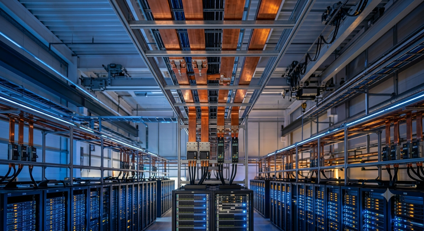
What Busbars Actually Are and Why They Matter Now
The term “busbar” describes a range of conductive hardware far wider than a single product category. At its most basic, a busbar is a metallic conductor copper or aluminium that carries high current between two points. In practice, the busbars deployed in modern data centers are precision-engineered components with defined geometry, controlled surface area, fixed connection points, and thermal management built into their physical form. A rigid copper busbar is not simply a cable replacement. It is a structured current path that allows designers to predict electrical behavior, mechanical behavior, and thermal behavior across the life of the installation.
Busway systems he overhead overhead power distribution infrastructure built around busbars extend this concept to facility-scale distribution. Sections arrive from the factory pre-engineered, then get lifted, aligned, supported, and joined on-site. Cable systems require tray or conduit installation, multiple cable pulls, dressing, cleating, bending radius control, termination, phase identification, and repeated labor at each connection point. Busway replaces much of that field work with a prefabricated assembly approach. The labor saving grows as designs move from moderate to high current. That speed matters when a hyperscale campus is under construction on a timeline measured in months rather than years.
Overhead vs. Underfloor: The Layout Debate
Data center designers choosing busbar distribution face a secondary decision about routing topology. Underfloor distribution routes power beneath raised floor tiles, leaving overhead space clear. It offers flexibility in equipment arrangement, since power access points can be positioned under any tile location. Overhead busbar distribution installs busbars and tap-off boxes along ceiling support structures, leaving the floor entirely free. Neither approach is universally correct. The choice depends on cooling strategy, rack layout, maintenance access preferences, and the physical geometry of each hall.
Overhead busbar has gained dominance in high-density AI facilities for a specific reason: it keeps the floor free for cooling infrastructure. Direct liquid cooling systems require floor-level pipework, manifold routing, and leak containment hardware. Adding underfloor cable systems to that environment creates maintenance access conflicts and thermal management complications. Overhead busway eliminates those conflicts by moving electrical distribution into a separate physical plane. Engineers access tap-off boxes from above the rack rows. The floor remains dedicated to cooling and structural support. That separation of electrical and cooling pathways has become a standard design principle in hyperscale AI halls.
Behind-the-Meter Generation and Internal Power Architecture
The shift to behind-the-meter generation has accelerated faster than most infrastructure analysts predicted two years ago. <p>According to datacenterHawk’s Q4 2025 market intelligence, providers in markets like Northern Virginia, Phoenix, Dallas, and Chicago face multi-year wait times for utility connections, expensive upfront costs for load studies, and million-dollar capacity deposits per megawatt in congested markets.</p> The response has been a bifurcation of the developer community: those who accept long timelines in exchange for utility reliability, and those who pursue on-site generation to reach operational status years earlier.
Natural gas has become the immediate bridge technology. Combustion turbines and reciprocating engines can be procured and deployed within 18 months a critical advantage when AI training workloads generate revenue only when compute is running. Chevron’s subsidiary announced a partnership with GE Vernova in early 2025 to develop multi-gigawatt co-located power plants serving colocation data centers. Williams committed over $5 billion to a power innovation model that places dedicated on-site power plants directly at data center campuses, bypassing the congested public grid entirely. Natural gas proposals for new U.S. data center power capacity tripled in 2025 compared to the previous year.
How Generation Architecture Shapes Distribution Design
On-site generation changes the electrical characteristics of the power that internal distribution systems must handle. Grid-connected facilities receive power that has been conditioned across transmission infrastructure, regulated by utility systems, and stabilized by the inertia of the wider grid. Behind-the-meter generation produces power with different stability profiles, particularly during transient load changes from AI GPU clusters that ramp from idle to full draw within milliseconds. Internal distribution infrastructure — busbars, switchgear, UPS systems, PDUs — must handle these transients without introducing voltage sag at the rack level that affects accelerator performance.
Busbar systems offer a specific advantage in this context. Their low-impedance current paths reduce resistive voltage drop between the generation source and the rack load. A high-resistance cable junction that causes an imperceptible performance variation at 8 kW per rack becomes a measurable voltage sag at 100 kW per rack under transient conditions. Rigid copper busbars with precision-machined connection surfaces and verified joint torque present consistent, low-resistance paths that cable systems cannot reliably match after years of thermal cycling and mechanical stress. The busbar is not merely a conductor — it is a voltage-stability component in a facility powered by its own generation assets.
Copper vs. Aluminium: The Material Debate
Copper has been the default busbar conductor in data center applications for decades. Its electrical conductivity is approximately 60 percent higher than aluminium’s per unit cross-section, which means a copper busbar of given dimensions carries more current than an equivalently sized aluminium conductor. For high-current applications where space is at a premium — overhead busway runs serving 100 kW racks in a tight ceiling plenum — copper’s conductivity advantage directly translates to smaller physical conductor sections for the same ampacity. Connection behavior also favors copper at high current. Copper maintains oxide-free contact surfaces more reliably than aluminium, which forms a resistive oxide layer that must be managed through careful connection preparation and anti-oxidant compounds.
Aluminium adoption has grown meaningfully in the busway market for reasons that are equally technical. Aluminium weighs roughly one-third as much as copper per unit volume. Overhead busway systems carry significant weight loads across long ceiling spans. A facility-wide aluminium busway installation reduces structural loading on overhead support systems, simplifies installation logistics, and in large builds, reduces material cost substantially — copper prices remained elevated through 2024 and 2025 amid supply chain pressure from EV manufacturing and grid infrastructure programs. The busway market recorded a 21 percent increase in aluminium-based busbar adoption compared with copper through the 2024–2025 period, driven directly by the weight and cost factors in large-scale hyperscale builds.
Hybrid Approaches in Practice
Practical busbar specification in modern data centers rarely treats copper and aluminium as mutually exclusive choices. Many facilities use aluminium for long feeder runs — horizontal spans from switchgear to zone distribution points across wide data halls — and copper for short, high-current rack-level connections where conductivity and connection integrity matter most. This hybrid approach optimizes the weight and cost profile of the overhead busway infrastructure while preserving the connection reliability that high-density racks require at the point where power enters the enclosure.
Schneider Electric’s I-Line Track busway, introduced in 2024, exemplifies the engineering direction. Its silver-plated copper busbars use dual-layer insulation and double-headed bolt connection technology that fractures at a pre-set torque, providing visual confirmation that joints are correctly tightened without requiring torque wrench verification on each connection. Belleville spring washers maintain consistent clamping force through thermal cycling — a detail that matters over years of operation when racks cycle between low and high GPU load dozens of times per day. The connection interface, not the conductor itself, is often where busbar systems fail in service. Engineering that detail correctly is what separates a robust fifteen-year busbar installation from one that requires remedial thermal imaging intervention within two years.
Monitoring, Maintenance, and Operational Intelligence
The busway installed in a data center built five years ago was largely passive — it carried current, and operators trusted it was working unless a fault appeared. Modern busway systems integrate monitoring hardware at tap-off boxes that report load current, phase balance, temperature, and energy consumption to DCIM platforms. That shift from passive conductor to instrumented asset changes the maintenance relationship fundamentally. Operators can see which rack rows are approaching their tap-box ampacity limits. They can identify which zones carry unbalanced three-phase loads that create neutral current and additional heating. They can track energy at the sub-row level, which supports both efficiency optimization and accurate tenant billing in colocation environments.
Thermal imaging remains the most reliable tool for detecting connection degradation in busbar systems. Annual inspections using infrared cameras identify hot spots at joints and tap connections before they develop into faults. Industry best practice recommends re-torquing busbar connections after several years of service in applications where the busbar experiences high thermal cycling — GPU facilities where racks shift between idle and full AI training load create exactly that condition. A joint that was correctly torqued during installation and has experienced thousands of heat-cool cycles may have relaxed marginally, enough to increase contact resistance and begin generating additional heat. Catching that condition during a scheduled infrared inspection prevents the kind of connection failure that causes a rack-level outage in a facility generating significant revenue per compute-hour.
DCIM Integration and Real-Time Visibility
Sunbird DCIM and similar platforms now integrate busway tap-box data into the same monitoring environment that tracks cooling, UPS, and server hardware. That integration matters for AI facility operations in ways that go beyond routine maintenance. GPU clusters under active training draw power in distinct patterns — ramp periods, sustained maximums, brief idle intervals between batches — that appear in tap-box current data as recognizable signatures. Operators who correlate power draw at the busway level with workload scheduling data can identify anomalous consumption patterns that indicate hardware degradation before compute performance drops. A GPU card drawing 15 percent above its typical load profile during a standard training job is likely developing a thermal management problem. The busway tap box that serves its rack provides the first evidence.
The move from cable-based distribution to intelligent busway also simplifies circuit adds during facility expansion. Traditional cable-based power systems require new cable installation and panel circuit additions whenever a rack is added to an occupied zone. Overhead busway with continuous-access slot designs allows tap-off boxes to connect at any point along the busway run without requiring new cable pulls or panel work. This design characteristic — the ability to add a tap box in hours rather than days — directly reduces the time between a colocation customer signing a contract and their rack receiving power. In a market where AI compute capacity generates revenue from the moment it is energized, that installation speed has measurable commercial value.
Scalability as a Design Philosophy
Data center development has shifted from the “build to maximum capacity at day one” model toward phased deployment strategies that add power infrastructure in parallel with demand growth. That shift has implications for the distribution architecture specified during initial construction. Overhead busway systems can accept additional tap-off boxes without facility shutdown in most configurations. Adding a busway extension section to serve a new row of racks is an hour’s work on a scaffold rather than a multi-day cable pulling operation. The modular, factory-prefabricated nature of busway sections means that the installed base can expand along a consistent design without the variability that field-installed cable systems introduce.
Operators pursuing this strategy do not need to install full-capacity busway infrastructure on day one. A facility designed for 50 MW of final capacity can begin with busway infrastructure rated for 15 MW of initial load, with physical space reserved in the overhead channel for additional busway sections as density grows. The busway’s plug-in design philosophy is what enables this approach — sections connect predictably, tap positions are standardized, and the installation behavior of the fifth busway section mirrors the first. That repeatability reduces commissioning time and eliminates the inspection uncertainty that accompanies large cable-based installations where individual conductors may have been routed differently by different installation crews.
The West London and Northern Virginia Effect on Internal Architecture
The interconnection delays in primary markets have done something that market forces alone might not have accomplished as quickly: they have made internal power distribution optimization a boardroom-level topic. When a facility’s power source is on-site generation rather than a utility connection, the efficiency of internal distribution directly determines how much of that generated power reaches computing hardware. Every percentage point of internal distribution loss is a percentage point of generation capacity that must be oversized to compensate. For a campus running on behind-the-meter natural gas generation at significant cost per megawatt-hour, internal distribution efficiency has direct financial consequences.
Busbar systems deliver measurable efficiency advantages over cable-based distribution at high current. Their lower resistance per unit length reduces I²R losses — the heat generated by current flowing through a conductor’s resistance. A rigid copper busbar with machined connection surfaces presents lower contact resistance than a bolted cable lug that may have been installed with variable torque and has accumulated surface oxidation over years of service. Across a high-density data hall running hundreds of racks at AI accelerator loads, those resistance differences accumulate into measurable power savings. Overhead busway systems also eliminate abandoned cables — a persistent source of impedance and airflow obstruction in facilities that have been reconfigured multiple times without removing legacy wiring.
The Procurement and Specification Challenge
Busbar specification in new data center construction must begin during electrical architecture design, not during equipment selection. The Uptime Institute’s 2025 survey data makes this requirement concrete: rack density targets drive busway ampacity requirements, which drive conductor sizing, which drive overhead structural loading calculations, which drive the building’s structural design. A facility designed around 9 kW average rack density with headroom for 30 kW outliers needs different overhead busway infrastructure than one targeting 80 kW average density for AI training racks. Discovering that distinction after structural steelwork is installed forces expensive remedial design work.
Procurement timelines for custom busbar sections — particularly long-run copper feeder busbars for large data halls — can extend across several months from specification to delivery. Material pricing for copper is subject to market fluctuations driven by global EV manufacturing and grid infrastructure competition, so projects that defer busbar procurement to late-stage decision-making face both lead-time risk and cost uncertainty. Best practice is to define busbar specifications during the schematic design phase, issue preliminary procurement inquiries when design development begins, and lock material commitments during construction documents — the same sequence that governs structural steel procurement on large industrial builds.
Qualification and Testing Requirements
Busbar assemblies destined for data center applications carry IEC 61439-6 and relevant regional standards that define testing and documentation requirements for low-voltage busway systems. Factory acceptance testing verifies that conductor cross-sections, insulation integrity, joint resistance, and temperature-rise performance meet specification before sections ship. For high-density AI applications where bus sections will carry currents approaching their rated maximums continuously, temperature-rise testing is particularly important — a busway section that meets its rated ampacity at the margin of its thermal envelope may not perform adequately in a ceiling plenum with restricted airflow.
Connection hardware qualification deserves independent attention. Silver-plated connection surfaces, torque-indicating fasteners, and spring-loaded clamping systems are not standardized across manufacturer product lines. A facility that mixes busway sections from different manufacturers — which sometimes occurs in retrofit projects where existing sections are retained — must verify that tap-off boxes and junction hardware are fully compatible at the interface level. Contact surface metallurgy, clamping force specifications, and thermal expansion coefficients must all be compatible to maintain low-resistance connections across the temperature range the joint will experience in service. Specifying a single-manufacturer busway system for each distribution zone eliminates most of these compatibility issues.
Small Modular Reactors and the Long-Term Power Architecture
Small modular reactors are moving from concept to early deployment as a behind-the-meter power source for data centers, and their introduction reshapes power architecture discussions in ways that extend beyond the reactor itself. Amazon Web Services secured a 17-year power purchase agreement for 1.92 GW from the Susquehanna nuclear facility in Pennsylvania in June 2025, signaling serious institutional commitment to nuclear-backed data center power. Google has partnered with Kairos Power targeting initial SMR deployment by 2030. Microsoft, Amazon, and Google are all investing in SMR ventures with direct relevance to data center power supply.
An SMR-powered campus operating behind the meter produces power with characteristics that differ from both utility grid supply and natural gas generation. Nuclear generation provides extremely stable baseload output with minimal frequency variation and high thermal inertia — it does not ramp up and down in response to load changes the way a gas turbine does. For data center internal distribution architecture, this means that voltage regulation and transient response management must be handled within the facility rather than relying on generator controls. Busbar systems in SMR-connected facilities must accommodate precise load management from distribution switchgear, with monitoring systems that track consumption at the rack level to support the demand-response flexibility that grid operators may require under co-located load arrangements.
Integrated Energy Systems and Distribution Design
The convergence of on-site generation, battery storage, and intelligent distribution creates data center power architectures that look increasingly like microgrids. Battery storage systems — deployed alongside natural gas turbines or as standalone assets in some markets — require connection to the same internal distribution infrastructure that serves compute loads. Busbar systems designed for AI rack loads must also accommodate the charge and discharge current profiles of large battery arrays without voltage disturbance at the rack level. This is not a trivial design requirement: battery storage at grid-support scale involves current magnitudes and transient profiles that can interact with the impedance of the distribution system in ways that were not present when the facility drew from a stable utility connection.
Engineers designing distribution architecture for behind-the-meter campuses increasingly treat the busbar system as part of an integrated power management network rather than a passive conductor. Real-time monitoring at tap-box level feeds data to energy management systems that can shift loads between zones, throttle non-critical workloads during generation constraints, and optimize storage charge cycles against compute demand patterns. The busbar is the physical foundation on which this intelligence operates. Its reliability, its low impedance, and its monitoring integration capability determine whether the energy management layer can function as designed. Facilities that retained cable-based distribution while adopting sophisticated behind-the-meter generation find that the distribution layer becomes the performance bottleneck that limits the value of the generation investment.
The Market Reality in 2026
The busway market reflects the infrastructure transition underway. The global data center busbars market was valued at $1.8 billion in 2024 and is projected to reach $3.75 billion by 2033. More than 65 percent of new data center facilities above 10 MW now deploy busway power distribution instead of traditional cable trays. Nearly 72 percent of new builds above 20 MW integrate busway systems rated between 800 amperes and 5000 amperes. Over 60 percent of new product launches between 2023 and 2025 feature higher ampacity ratings, integrated IoT monitoring, and reduced installation footprints — reflecting the direction the market is demanding.
High-density AI clusters operating above 30 kW per rack have increased substantially since 2022, directly accelerating busway adoption. Hyperscale cloud providers and colocation facilities drove the initial transition from copper cable trays to busway systems over the past decade, but the AI infrastructure surge has extended that transition into facilities that previously had no commercial reason to upgrade their distribution architecture. A colocation operator in a secondary market serving enterprise AI customers competes on the same infrastructure metrics as a hyperscale cloud provider. The competitive standard for power distribution infrastructure has risen across the entire industry, not just at its hyperscale apex.
The Manufacturers Responding to Demand
Established electrical infrastructure manufacturers have repositioned their product lines around the AI data center opportunity. Schneider Electric’s introduction of the I-Line Track in April 2024 targeted precisely the flexibility and density demands of AI-optimized halls. Vertiv’s PowerBar busway system supports the overhead distribution configurations that liquid-cooled AI facilities require. ABB and Siemens maintain busway product families with ampacity ratings that extend into the thousands of amperes for primary distribution runs. Legrand reported a 24 percent revenue increase from its AI-focused data center infrastructure portfolio in the first half of 2025, with its data center revenue projected to exceed €2 billion for the full year. The commercial signal from infrastructure manufacturers is unambiguous: busbar systems are the growth segment within data center electrical infrastructure, and the investment in product development reflects where the industry is heading.
Competitive dynamics are shaped by consolidation and targeted product innovation. Companies are using acquisitions, partnerships, and new busway designs to win hyperscale and AI workload contracts. The result for data center operators is a wider choice of qualified busway products with better monitoring integration, higher ampacity ratings, and faster installation than was available just three years ago. The engineering challenge is not finding capable products — it is specifying the right system for a facility whose density requirements may change significantly between design and operation, and whose power source may shift from utility grid to on-site generation as behind-the-meter strategies mature.
Thermal Management at the Busbar Level
Every conductor generates heat when carrying current. The relationship is not linear: doubling current quadruples heat generation because the relationship follows current squared multiplied by resistance. This means that the thermal management of busbar systems in high-density facilities is a first-order engineering problem, not a secondary concern. Copper’s exposed surface area dissipates heat through natural convection when busway is installed with adequate spacing between runs and between the busway and adjacent obstructions. Enclosed sandwich-type busway relies on the thermal properties of its insulation and housing to conduct heat outward. Open-channel busway designs allow direct airflow over conductor surfaces, supporting passive cooling at higher current densities.
AI data center ceiling environments complicate thermal management in a specific way. Hot aisle containment systems, which direct hot exhaust air from server rows toward cooling units, can raise ceiling plenum temperatures significantly above ambient room temperature in poorly designed facilities. Busway runs through hot zones must be rated for the elevated ambient temperature, because the same current in a warmer environment produces higher conductor temperatures that reduce the effective ampacity of the installation. Engineers specifying overhead busway in AI facilities should define the expected ceiling temperature range — accounting for containment design, cooling strategy, and redundancy scenarios — and verify that specified busway maintains full ampacity at the maximum expected ambient.
Liquid Cooling Integration and Busbar Proximity
Direct liquid cooling — where coolant flows through cold plates in direct contact with processor packages — introduces liquid into the physical environment immediately adjacent to high-current electrical distribution hardware. The proximity of liquid manifolds and busbar runs in AI data hall ceiling structures requires explicit design coordination. Leak detection systems must cover the zones where liquid cooling pipework passes beneath or parallel to busway runs. Busway housing designs for these environments should be sealed against liquid ingress at the IP rating appropriate to the splash zone classification of the installation area.
Indirect liquid cooling architectures — rear-door heat exchangers, in-row coolers — present a different coexistence challenge. Condensation from cooling units operating near the dew point of the room air can accumulate on busway surfaces if the cooling system is improperly commissioned. Anti-condensation measures in the cooling system design, combined with busway housing that provides appropriate IP protection, are the standard engineering response. The combination of AI rack densities, liquid cooling infrastructure, and high-current busbar distribution systems is new enough that best practices are still being established through field experience. Data center operators who document their installation conditions and commissioning findings contribute to an industry knowledge base that is still developing in real time.
What Comes After the Copper Transition
NVIDIA’s 800V HVDC architecture signals a distribution stack that looks substantially different from today’s standard data center power chain, utility transformer, UPS, switchgear, PDU, cable runs, rack power shelf, server power supply. At 800V distribution, the dedicated power rack adjacent to each compute rack replaces the in-rack power shelf. The HVDC busbar connecting the power sidecar to the compute rack carries current at a fraction of the amperage that a 54V system requires for equivalent power. The compute rack’s internal bus converters handle the step-down to 48V and lower for the accelerator hardware. For facility-level busbar infrastructure, the 800V architecture reduces the current-carrying requirement of overhead busway runs while increasing the voltage rating requirement. Most current data center busway is rated for 600V or 1000V — within the range need for 800V DC distribution.
Standardization and the Open Compute Influence
The Open Compute Project has been the primary venue for developing shared specifications around rack power architecture, and its influence on busbar standardization is growing. OCP ORv3 specifications define connector interfaces, power shelf form factors, and busbar geometry for 48V rack distribution in considerable detail. As the industry moves toward HVDC architectures, OCP working groups are developing specifications that will define the physical interfaces between 800V power sidecars and compute racks — specifications that will shape busbar connection hardware design across the entire data center supply chain. Co-authored specifications from Google, Meta, and Microsoft for the Mt. Diablo power rack sidecar define disaggregated power delivery beyond traditional 48V configurations. Delta Electronics’ 800VDC AI Power Cube ecosystem, developed with NVIDIA, targets 1.1 MW-scale AI racks.
Redesigning for a Generation That Has Already Arrived
The data center industry’s internal power distribution story is not about what might happen when AI workloads eventually arrive at scale. It is about the engineering response to demands that are operational right now. Behind-the-meter natural gas generation is powering live facilities in Texas and the American Southeast. Interconnection queues in Northern Virginia are not a forecast they are a current constraint that developers face today when trying to break ground on new capacity. Busbar systems are the infrastructure response to this present reality. They carry more current per unit of physical cross-section than cable systems, dissipating heat more effectively through defined geometry and consistent spacing.
They install faster, reconfigure faster, and monitor more precisely than cable-based alternatives. Their modular design supports the phased build approach that matches power infrastructure investment to actual load growth. Their low-impedance construction reduces distribution losses in facilities where every watt of efficiency carries direct financial weight when power comes from on-site generation rather than an unlimited utility supply. The transition from copper cable systems to busbar distribution is already underway in every market that matters — Northern Virginia, West London, Singapore, Tokyo, Frankfurt. The pace of that transition is set not by vendor roadmaps or analyst forecasts but by the physical demands of the hardware being installed in facilities right now. An NVIDIA Rubin Ultra rack demanding approaching 900 kW has no viable cable-based power distribution solution. The engineering answer is busbar, in one form or another, from the facility’s generation source to the point of load.


