
The Hall That Must Serve Two Eras Simultaneously
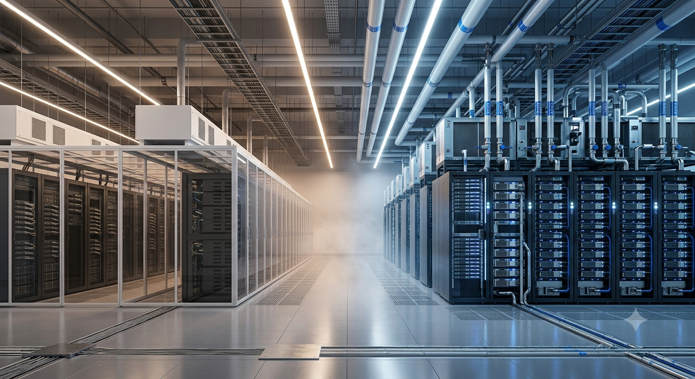
Walk into a mixed-density data hall today and you encounter a paradox. One row holds legacy enterprise servers drawing 8–10 kW per rack. Three rows away, GPU clusters consume 100 kW or more per rack. Both workloads matter commercially. Both generate revenue. Neither can be switched off to accommodate the other. The engineering task is not to choose between cooling strategies — it is to architect a system where both coexist without thermodynamic interference.
This is the defining challenge for colocation operators, enterprise IT managers, and hyperscale developers managing existing real estate. Purpose-built AI factories dominate industry headlines. However, more than 70 percent of global data center capacity resides inside existing buildings. That installed base cannot simply be replaced. Grid interconnection queues stretch to seven years in primary markets. Land entitlement in dense metros takes years. Consequently, the brownfield estate — aging, air-cooled, and designed for a different era of rack density — has become the frontier where the AI transition actually happens. The thermodynamic compromise that results is neither elegant nor simple. It demands a layered mechanical architecture, intelligent control systems, and a financial model that extracts maximum value from existing infrastructure without stranding millions in sunk capital.
Why Air Cooling Hits a Hard Physics Limit
Air cooling operates within a fundamental thermodynamic boundary. Beyond approximately 41.3 kW per rack, the volume of chilled air needed to remove heat exceeds what any practical plenum design can deliver. Airflow velocities that would theoretically keep pace create acoustic levels incompatible with operations staff and cause mechanical turbulence that disrupts cooling patterns. Hot-aisle containment extends useful air-cooled performance — but it does not change the underlying physics. NVIDIA’s H100 GPU dissipates more than 700 watts per chip. A standard four-GPU inference server generates over 2.8 kW from GPUs alone, before accounting for CPUs, memory, networking hardware, and power supply losses.
As AI accelerator generations advance, those figures climb further. NVIDIA’s roadmap projects per-chip power consumption reaching 1,500 watts by 2026. An eight-GPU training server at that power level exceeds the cooling capacity of every practical air-cooled rack design. Air cooling’s operational efficiency profile also deteriorates at high density. Traditional air-cooled facilities consume cooling infrastructure representing approximately 40 percent of total facility energy use. That proportion climbs in high-density zones where CRAC or CRAH units run at peak output continuously. The PUE penalty from forcing air-cooled infrastructure to manage densities above its design envelope is measurable — and expensive.
Legacy Infrastructure Doesn’t Simply Disappear
The operational reality complicating the physics argument is tenancy. A colocation operator cannot simply remove air-cooled rows to install liquid cooling. Existing enterprise contracts run for three to five years. Legacy workloads — databases, ERP systems, financial applications, collaboration platforms — generate consistent, predictable revenue. Displacing those tenants to chase high-density GPU contracts introduces vacancy risk and potential lease break liabilities. Brownfield facilities therefore face a commercial mandate to maintain air-cooled capacity while simultaneously introducing liquid-cooled zones for new AI tenants.
Moreover, existing air-cooled infrastructure carries embedded capital. CRAC units, raised floors, hot-aisle containment systems, and chiller plants represent investments that operators depreciate over long asset lives. Writing down that infrastructure prematurely creates accounting losses that damage facility-level returns and investor confidence. The thermal compromise — designing a system where both cooling modalities coexist — therefore reflects a commercial necessity, not merely an engineering preference. The goal is extracting full remaining value from legacy cooling assets while building the liquid-cooled capacity that AI workloads demand.
The Thermodynamics of Coexistence
Running two distinct thermal environments inside one data hall creates heat plume interference patterns that designers must model before committing to physical infrastructure. Air-cooled rows generate hot exhaust at 35–45°C. That exhaust, if not fully captured by containment, migrates across the hall and affects adjacent zones. Liquid-cooled AI rows — where direct-to-chip systems remove 60–80 percent of server heat into the coolant loop — reject residual heat through rear-door heat exchangers or top-of-rack exhaust at elevated temperatures. In a mixed hall, those two thermal signatures interact.
Computational fluid dynamics modeling has become a prerequisite for mixed-density hall design. CFD tools simulate airflow patterns, pressure differentials, and hot spot formation before any physical modification begins. The output identifies which air-cooled rows face recirculation risk from adjacent liquid-cooled exhaust, which cooling units require additional capacity, and where containment modifications can isolate thermal zones effectively. CFD modeling also reveals counterintuitive outcomes — such as liquid-cooled rows inadvertently pulling cold air away from air-cooled zones by creating low-pressure regions at their intake faces. Addressing those interactions in software costs weeks. Addressing them after installation costs months and significant capital.
Temperature Set Points and the Compatibility Window
Legacy air-cooled operations typically maintain inlet temperatures between 18°C and 27°C, following ASHRAE A1 and A2 class specifications. Liquid-cooled direct-to-chip systems operate effectively with facility water supply temperatures between 18°C and 45°C — a broader thermal window that offers flexibility. However, that flexibility creates a management challenge in a shared chilled water plant. A chiller plant producing 12°C supply water for air-cooled CRAH units delivers water that is colder than liquid-cooled loops require, increasing chiller energy consumption unnecessarily.
Warm-water liquid cooling — designing the liquid loop to operate at higher supply temperatures, typically 30–45°C — allows chillers to operate at improved efficiency or to be bypassed entirely in favorable ambient conditions. However, introducing warm-water loops into a facility with a chilled-water plant built for low supply temperatures requires either dedicated secondary circuits or a valve architecture that segregates supply temperatures to different zones. That segregation is achievable through intelligent piping manifolds and zone-level control valves. Furthermore, it is one of the first mechanical decisions that determines whether hybrid cooling delivers its theoretical efficiency gains or merely adds complexity without improving PUE.
The CDU: Traffic Controller for Hybrid Thermal Flows
The coolant distribution unit is the mechanical and control heart of any liquid cooling deployment inside a hybrid data hall. It functions as the interface between facility-level water systems and rack-level cooling loops. On the facility side, it connects to chilled water supply and return headers. On the IT side, it connects to cold plate manifolds or rear-door heat exchanger circuits through quick-disconnect fittings. Between those two connections, it manages flow rates, supply temperature, supply pressure, and leak detection — continuously and in real time.
In a mixed-density hall, the CDU performs a specific additional function: it isolates the liquid cooling circuit from the facility chilled water plant. That isolation prevents coolant contamination events — such as a leaking cold plate introducing server-side particulates into facility water — from affecting the broader cooling plant. It also allows the liquid loop to operate at different temperatures than the facility chilled water supply, using heat exchangers inside the CDU to transfer thermal energy between circuits. Eaton’s ROL4000 CDU, for example, provides 2 MW of cooling at a 3°C approach temperature, delivering up to 80 PSI of available pressure to drive flow through high-performance cold plate loops. That pressure specification matters: GPU cold plates with dense microchannel geometries require precise flow management that general facility water circuits cannot deliver without a dedicated CDU.
Intelligent CDU Control in Practice
Modern CDUs are not passive heat exchangers. They carry embedded controllers that communicate with DCIM platforms, building management systems, and rack-level temperature sensors. That control integration enables dynamic adjustment of coolant flow rates in response to GPU workload changes — reducing pump energy during periods of lower AI training intensity and increasing flow when training runs push chips toward thermal limits. The intelligence layer also enables predictive leak detection, tracking differential pressure across the secondary loop to identify developing flow restrictions before they cause thermal events.
DCX introduced an 8 MW CDU in January 2026, designed specifically for facility-level deployment in large-scale AI data halls. That capacity rating — 8 MW per unit — reflects how the CDU market has evolved from rack-level accessories to primary infrastructure components. Flex introduced a modular rack-level CDU in September 2025, targeting scalability for AI and HPC workloads. Together, these product introductions reflect a market that has moved from experimental to standardized within approximately eighteen months. The hybrid CDU segment is expected to grow at a CAGR of 22.4 percent through 2033, according to Grand View Research. Operators who treated CDU selection as a secondary procurement decision are increasingly recognizing it as a primary engineering constraint.
Rear-Door Heat Exchangers: The Transition Technology
Rear-door heat exchangers occupy a strategically important position in hybrid cooling architecture. They attach directly to existing rack enclosures, replacing standard rear doors with heat exchanger panels through which chilled water circulates. Server fans continue to push hot exhaust air through the RDHx panel, where the thermal energy transfers to the water circuit. The servers themselves require no modification. Their air-cooling mechanisms remain intact. However, the heat they generate enters the liquid circuit rather than the raised floor return air plenum.
This characteristic makes RDHx the practical first step for brownfield facilities attempting to serve higher-density workloads without a full liquid cooling build-out. A rack drawing 30–50 kW — above the safe operating threshold for air cooling but below the regime where direct-to-chip cold plates are mandated — can be served effectively by RDHx. Motivair’s ChilledDoor system is specifically designed for this intermediate density range, stabilizing rack temperatures under peak AI workloads while coexisting with air-cooled rows on either side. Schneider Electric’s retrofit guidance for AI workloads identifies RDHx as the transition technology that enables brownfield operators to serve customers with moderate AI inference loads while planning more comprehensive liquid cooling deployment.
RDHx Limitations at True AI Density
RDHx performs well up to approximately 30–50 kW per rack under typical configurations. Beyond that threshold, the approach temperature between server exhaust air and chilled water — the thermal driving force that enables heat transfer — limits RDHx effectiveness. Air is a poor thermal medium at very high heat fluxes. The heat exchanger panel cannot remove 100+ kW from a rack row without either extremely low chilled water supply temperatures or impractically large panel surface areas. Consequently, RDHx functions as a bridge technology rather than an endpoint solution for AI factory workloads.
Operators who deploy RDHx in mixed halls today need a clear upgrade pathway for rows that will eventually carry higher-density GPU loads. Designing piping infrastructure for RDHx at first deployment, then upgrading to direct-to-chip cold plate circuits served by the same piping headers, is the approach that avoids stranded capital in cooling infrastructure. The manifold and return headers installed for RDHx can typically accept cold plate circuits with CDU additions, provided piping sizing and pressure ratings were specified with that upgrade path in mind. That foresight in initial specification is what separates a phased retrofit roadmap from a series of expensive one-time fixes.
Direct-to-Chip Cooling: The AI Workload Standard
Direct-to-chip cooling places cold plates in direct thermal contact with CPUs, GPUs, memory modules, and voltage regulators. Coolant — typically deionized water or a water-glycol mixture — circulates through microchannels machined into the cold plate surface, absorbing heat at the source before it ever enters the rack airspace. The thermal efficiency of this approach is fundamentally superior to air cooling because liquid has a heat capacity approximately 3,500 times greater than air per unit volume. A direct-to-chip system removes 60–80 percent of server heat through the liquid circuit. Residual heat from power supplies, SSDs, and networking hardware continues to require air handling — meaning direct-to-chip does not eliminate air infrastructure entirely, but it reduces its burden dramatically.
Direct-to-chip cooling supports rack densities of 50–120 kW or above, depending on cold plate design and coolant flow rates. The Open Compute Project’s ORv3 48V specification for AI server racks assumes direct-to-chip cooling as the baseline for racks above approximately 30 kW. AMD and NVIDIA both recommend direct-to-chip solutions for their current AI accelerator families. Microsoft began fleet deployment of direct-to-chip cooling across Azure campuses in July 2025. Direct-to-chip now holds approximately 47 percent of the liquid cooling market share, reflecting its position as the dominant architecture for enterprise AI infrastructure.
Integration Complexity in a Legacy Hall
Installing direct-to-chip cooling inside an existing air-cooled hall introduces engineering complexity that pure greenfield deployments avoid. Existing raised floors may lack the structural capacity to support CDUs and coolant distribution manifolds without reinforcement. Existing ceiling heights may constrain overhead piping routes for supply and return headers. Floor penetrations for liquid piping require leak-containment strategies — including secondary containment channels and floor drains — that were not part of the original facility design. Electrical infrastructure must be reviewed for compatibility with the higher power densities that liquid-cooled AI racks draw. All of this must happen while air-cooled rows on either side of the liquid zone remain fully operational, under live SLA commitments.
The phased deployment model addresses this complexity by treating each direct-to-chip installation as a discrete project with defined scope, timeline, and risk management. A single row or zone can be converted to liquid cooling while adjacent air-cooled rows continue operating. Temporary containment during piping installation, pre-fabricated manifold assemblies tested off-site, and rack-by-rack CDU commissioning reduce the exposure window for each phase. Meta’s Prineville facility executed exactly this model over an 18-month conversion period, maintaining operations throughout while ultimately achieving a PUE reduction to 1.09 and tripling compute density.
Immersion Cooling: The High-Ceiling Option
Immersion cooling places entire server assemblies — or individual compute modules — directly into dielectric fluid. Single-phase immersion uses mineral oil or synthetic fluid that remains liquid throughout the process. Two-phase immersion uses engineered fluids that boil at the chip surface, absorbing latent heat before condensing and returning to the tank. Both approaches remove effectively 100 percent of server heat into the fluid, eliminating the residual air handling requirement that direct-to-chip systems retain. Rack densities in immersion systems commonly reach 100–200 kW per tank or above.
In a mixed-density brownfield hall, immersion tanks introduce a more significant infrastructure disruption than direct-to-chip cold plates. Tanks require structural floor loading well above legacy raised-floor specifications. They require fluid management infrastructure — fill stations, monitoring systems, and fluid quality control equipment. Servers must be removed from existing rack enclosures to enter immersion tanks, which adds migration complexity for operators converting active workloads. Consequently, immersion cooling in brownfield deployments typically occurs in dedicated zones separated from legacy air-cooled operations, rather than interspersed through existing rows.
The Zoning Strategy for Immersion
The practical approach for brownfield immersion deployment is hall zoning — designating specific physical zones within the facility for immersion infrastructure, with clear demarcation from air-cooled and direct-to-chip zones. That zoning strategy requires upfront floor reinforcement in the immersion zone, independent piping circuits for dielectric fluid management, and containment barriers that prevent fluid migration to adjacent zones. A 25 MW colocation facility with a hybrid cooling architecture can configure 5 MW of traditional hot-aisle contained air cooling for enterprise workloads, 3 MW of immersion for extreme-density AI training, and intermediate zones served by direct-to-chip or RDHx for mid-density AI inference. This tiered zoning model — matched to the thermal profile of each customer segment — is the architecture that colocation operators implementing multi-tenant AI strategies are deploying in practice.
The DCIM Control Layer: Making Hybrid Systems Intelligent
A hybrid cooling hall with air-cooled zones, RDHx rows, direct-to-chip CDU circuits, and immersion tanks presents a monitoring challenge that exceeds the capability of conventional building management systems. Each cooling technology generates different sensor streams — CRAH unit discharge temperatures, CDU supply and return temperatures, cold plate outlet temperatures, tank fluid temperatures, and ambient hall temperatures across multiple zones. Correlating those streams into a unified operational picture requires a DCIM platform capable of ingesting data from multiple vendor systems simultaneously.
Modern DCIM platforms — including tools from Vertiv, Schneider Electric, and Nlyte — integrate cooling system data with IT load data at the rack level. That integration enables automatic identification of thermal anomalies: a rack whose liquid cooling loop return temperature rises faster than neighboring racks may indicate a cold plate flow restriction. A zone where air temperature rises without a corresponding increase in IT load may indicate a CRAH unit failure. The value of unified monitoring in a hybrid hall scales with the number of distinct cooling zones. Operators managing a single cooling technology across a uniform hall can use simpler systems. Those managing three or four distinct cooling modalities across the same physical space need DCIM integration as a baseline operational requirement.
Predictive Control and Dynamic Load Balancing
Beyond monitoring, the control layer enables dynamic optimization of cooling resources across the hybrid hall. AI-driven energy management systems can shift chilled water flow between zones based on real-time IT load profiles. A zone hosting AI training runs that ramp from idle to peak in milliseconds needs coolant supply prioritized during the training window. The air-cooled enterprise zone, carrying stable database workloads, needs consistent supply but without the rapid response requirement of the liquid-cooled AI zone. Dynamic flow balancing reduces total pump energy across the facility while maintaining thermal compliance in each zone.
Enabled Energy’s NextField advisory framework specifically identifies fault detection and diagnostics — FDD — as a critical tool for hybrid retrofit management. FDD analyzes sensor data patterns to detect equipment degradation before failures occur. In a hybrid hall, this allows operators to anticipate CRAH unit failures that would cascade into the air-cooled zone, CDU pump wear that would reduce liquid cooling capacity in a GPU cluster zone, and heat exchanger fouling that would increase approach temperatures and reduce cooling effectiveness. Predictive maintenance enabled by FDD extends equipment lifetimes, reduces unplanned downtime, and lowers total operational cost across a facility that cannot easily take zones offline for planned maintenance.
The Financial Framework for Brownfield Hybrid Retrofits
The financial case for brownfield hybrid retrofits rests on three structural advantages. First, the existing shell, foundations, and utility corridors are already depreciated. Reusing them eliminates 15–30 percent of build cost compared to a greenfield project on comparable land. Second, brownfield projects reach revenue generation in 12–24 months from initiation, against 24–48 months for greenfield builds. Third, phased liquid cooling deployment — rack by rack, zone by zone — allows capital expenditure to track closely with revenue, avoiding the large upfront exposure of building greenfield capacity ahead of contracted load.
Brownfield retrofits targeting high-density AI zones generate attractive return profiles. Standard redevelopment projects deliver IRRs in the 10–14 percent range. Energy-integrated or high-density AI retrofits with premium AI colocation pricing achieve IRRs approaching 18 percent, according to DataCenter Invest’s portfolio analysis. Those returns reflect both the revenue uplift from higher-density, higher-margin AI tenants and the avoided capital cost of greenfield development. Retrofit costs for liquid cooling installation run approximately $2–3 million per megawatt — significant, but substantially below the full construction cost of equivalent greenfield liquid-cooled capacity when land, structural work, and utility connections are included.
The Three-Phase Retrofit Roadmap
Successful brownfield hybrid cooling deployments follow a structured phased approach that manages capital deployment, operational risk, and tenant continuity simultaneously. Phase one targets quick wins — blanking panel installation, in-row cooling additions, hot-aisle containment improvements, and retro-commissioning of existing CRAH units. These interventions recover five to ten percent of stranded capacity with minimal capital and no operational disruption. They demonstrate performance improvement to existing tenants and establish the measurement baseline for subsequent phases.
Phase two deploys targeted capital investment. UPS system upgrades, power distribution improvements, and central cooling plant optimization address the infrastructure constraints that limit how much density the facility can serve. This phase may also introduce RDHx in rows identified for density upgrades, creating the first liquid circuits inside the hall and establishing the operational processes for liquid cooling management before higher-complexity direct-to-chip systems arrive. Phase three integrates direct-to-chip cooling and CDU infrastructure for AI cluster zones. By this point, operations teams are experienced with liquid systems. Tenants are contracted. The capital being deployed has a clear revenue justification. Equipment lead times — which can exceed 50 weeks for large CDUs and specialized cooling components — have been accounted for in the project schedule.
Stranded Asset Risk: The Capital Question Operators Must Answer
The risk that brownfield operators must price explicitly is stranded asset formation. Legacy CRAC units, raised floors, chiller plants, and underfloor cable infrastructure all carry book value that assumes continued productive use. A retrofit that replaces legacy cooling infrastructure before its accounting life has expired generates a write-down. If liquid cooling zones displace air-cooled zones that still have contracted tenants, the revenue model behind the original infrastructure investment disappears before the capital is recovered.
Operators managing this risk use depreciation analysis alongside retrofit planning. Infrastructure approaching the end of its accounting life — 12 to 15 years for major cooling plant in many frameworks — can be replaced without significant write-down impact. Infrastructure with substantial remaining book value requires either a deferred replacement schedule or a revenue model for the legacy zone that remains profitable through its accounting life while liquid cooling zones expand around it. Jurisdictions that mandate PUE or efficiency thresholds for continued operation — as some EU member states are beginning to do under national transpositions of the Energy Efficiency Directive — create a different risk: legacy air-cooled infrastructure that cannot meet efficiency thresholds becomes a regulatory liability rather than merely an underutilized asset.
The Revenue-Per-Square-Foot Calculation
The fundamental financial logic behind hybrid cooling retrofit investment is revenue-per-square-foot improvement. A legacy air-cooled data hall generating revenue from 8 kW per rack at standard colocation rates produces a defined revenue density. Converting a portion of that hall to serve 100 kW per rack at AI colocation premium pricing multiplies revenue per unit floor area significantly — even accounting for the capital cost of liquid cooling installation and the reduction in rack count that higher-density configurations sometimes require.
Forward-thinking operators are using this revenue-per-square-foot model explicitly when evaluating which zones within a mixed-density portfolio merit liquid cooling investment and at what pace. Zones with high AI tenant demand, favorable floor loading, and proximity to existing water infrastructure generate the strongest returns on liquid cooling investment. Zones with structural constraints, remote utility connections, or strong legacy tenant occupancy warrant continued optimization of air-cooled performance rather than forced liquid conversion. The discipline to match retrofit investment to facility-specific economics — rather than applying a uniform conversion strategy across a heterogeneous portfolio — is what distinguishes operators who will extract maximum value from their brownfield estate from those who will discover that not every facility was worth retrofitting.
The Operational Reality of Living in Both Worlds
A mixed-density hall carries mixed SLA commitments. Enterprise air-cooled tenants hold contracts specifying temperature and humidity ranges, power delivery guarantees, and uptime commitments. AI tenants hold contracts that may specify cooling water supply temperature, rack-level power delivery, and GPU thermal compliance. Those commitments are monitored by different systems, enforced through different contract mechanisms, and subject to different remediation requirements if breached. Operations teams managing a hybrid hall must simultaneously understand both cooling domains, interpret sensor data from different systems, and respond to failure scenarios in either zone without affecting the other.
Cross-training operations staff on both air-cooled and liquid-cooled systems has become a staffing requirement for hybrid facilities, not a preference. Technicians who understand only CRAH units and raised floor plenum management cannot safely manage a CDU fault in a liquid-cooled GPU zone. Conversely, specialists in liquid cooling who lack context on air containment strategies can make adjustments that inadvertently disrupt air-cooled zone thermal performance. The hybrid hall demands genuinely hybrid operational capability — and the training investment to build that capability must appear in the financial model for brownfield retrofit programs.
The Competitive Position a Hybrid Hall Creates
A brownfield data hall that successfully integrates air and liquid cooling layers occupies a differentiated competitive position that neither pure air-cooled nor purpose-built liquid-cooled facilities can replicate. It can serve legacy enterprise tenants who prefer air-cooled environments and who value existing network connections in an established facility. Simultaneously, it can serve AI tenants who need high-density liquid-cooled capacity with the speed-to-power advantage that brownfield facilities carry over greenfield builds. That dual-market capability — combined with the avoided cost of greenfield construction and the accelerated time to revenue — creates a product that is increasingly attractive to institutional investors seeking yield from digital infrastructure.
The market for AI-optimized colocation services continues to deepen. Colovore secured $925 million to offer racks up to 200 kW per rack. The liquid cooling market reached $5.52 billion in 2025 and is forecast to reach $15.75 billion by 2030. Organizations that deploy hybrid cooling now build operational maturity with liquid systems while the market matures further. That experience advantage — knowing how CDUs behave under sustained GPU training loads, how RDHx performs at the edge of its density envelope, and how mixed-zone DCIM monitoring surfaces actionable operational data — becomes a durable differentiator as AI workloads continue their migration from hyperscale-only deployments into the broader enterprise colocation market.
Engineering the Thermal Compromise Without Accepting the Compromise
The mixed-density data hall is not a transitional problem awaiting a clean solution. It is a permanent condition of a market where infrastructure lifetimes span 15–20 years and compute hardware generations span 18 months. The gap between those timescales means every significant data center will host multiple generations of equipment with different thermal profiles simultaneously. The engineering challenge is not to eliminate that gap — it is to manage it profitably without sacrificing either thermal performance or capital efficiency. Hybrid cooling architecture, intelligently designed, achieves exactly that. RDHx bridges the gap between legacy air cooling and full liquid deployment, serving intermediate density workloads without replacing functional infrastructure. Direct-to-chip CDU circuits handle AI training densities with the thermal precision that GPU workloads demand. Immersion zones accommodate the highest-density configurations where even direct-to-chip reaches its limits.
A unified DCIM control layer ties those disparate systems into a single operational picture that operators can manage predictably. And a phased financial model ensures that each capital commitment tracks closely with contracted revenue, preventing the stranded asset formation that unmanaged hybrid retrofits create. The operators who execute this architecture deliberately — who map thermodynamic zones before touching a screwdriver, who specify CDU pressure ratings with cold plate evolution in mind, and who design piping headers for the next technology rather than only the current one — will hold the most commercially durable positions in the data center market through the remainder of this decade. The thermal compromise does not have to mean accepting inferior performance in either domain. Done correctly, it means owning a facility that can serve every compute era as it arrives.


