
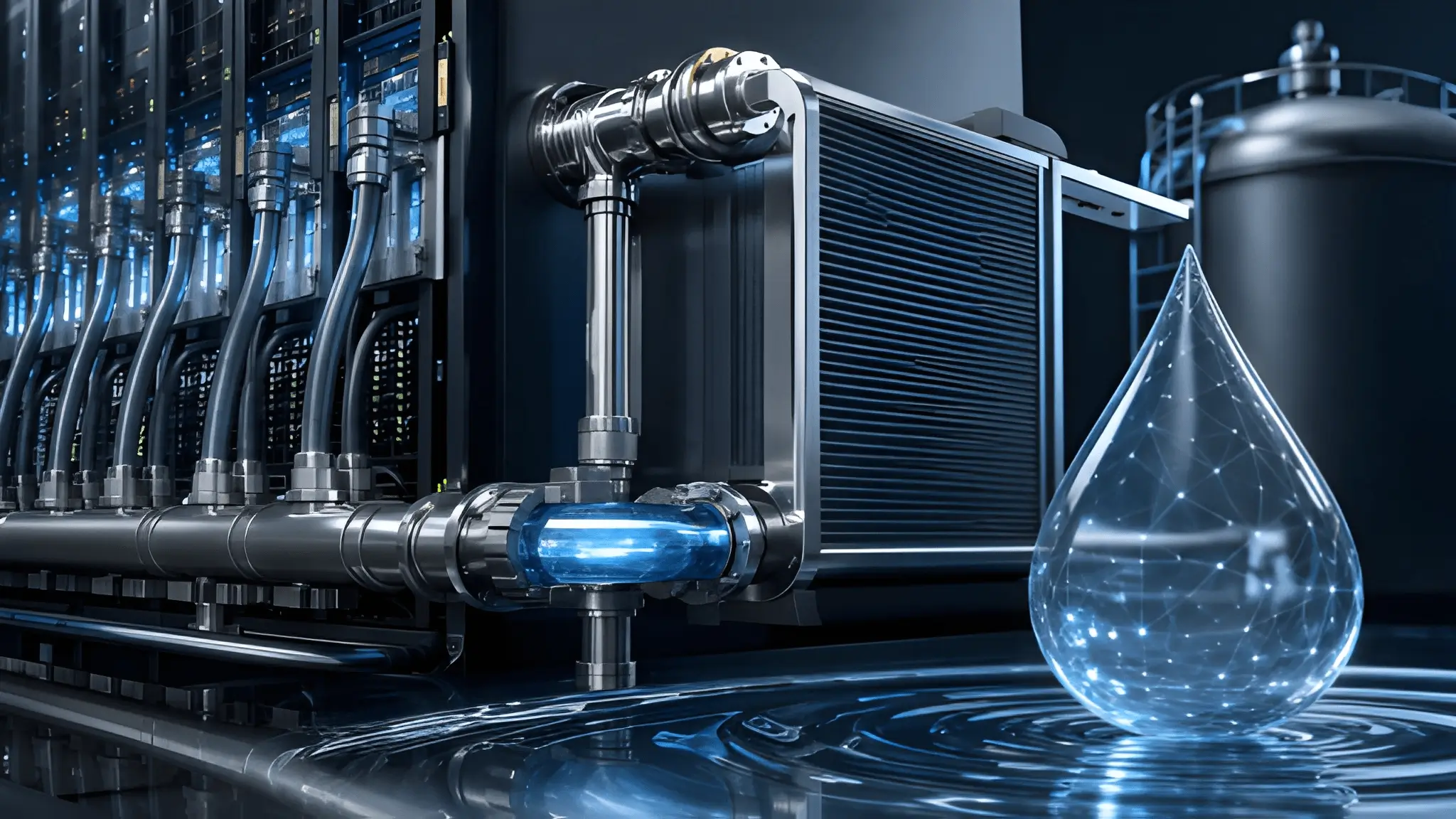
Modern compute infrastructure now places hydraulic engineering in the same decision framework as electrical capacity and thermal architecture. AI accelerators continue pushing rack power toward levels that force operators to evaluate every litre of circulating water with the same discipline applied to every kilowatt of incoming power. Cooling hardware may appear capable of supporting larger thermal loads on specification sheets, yet supporting infrastructure often determines practical deployment limits long before silicon reaches its thermal envelope. Project teams therefore spend increasing effort modelling pressure losses, pipe velocities, exchanger capacity, and facility hydraulics during early site selection instead of treating cooling as a downstream mechanical exercise. Engineering conversations increasingly shift from component efficiency toward system-wide transport capability because heat removal depends on moving energy through fluid rather than simply collecting it at the processor package.

The Pipe Behind the Plate: Flow-Rate Math That Breaks at 300kW
Single-phase liquid systems remove heat according to a straightforward relationship between coolant flow, temperature rise, and fluid heat capacity, making hydraulic design just as important as thermal performance. Higher rack densities require larger coolant volumes unless operators accept greater temperature differences across cold plates and associated components. Increasing flow does not occur without consequence because pressure losses rise throughout manifolds, flexible hoses, valves, and distribution branches as velocity increases. Pump selection therefore becomes a balance between available head pressure, acceptable operating efficiency, vibration limits, and long-term reliability instead of a simple capacity decision. Engineers frequently evaluate whether existing distribution piping provides sufficient hydraulic capacity for higher-density liquid cooling deployments because legacy infrastructure may require modification to support increased coolant flow and pressure requirements. Hydraulic resistance consequently becomes an infrastructure constraint rather than merely a mechanical design consideration.
Flow calculations become increasingly demanding as rack densities continue to rise because maintaining adequate coolant delivery requires careful balancing of flow rate, pressure drop, pipe sizing, and acceptable fluid velocity throughout the distribution network. Simply increasing pump speed rarely provides an efficient solution because higher differential pressure also raises energy consumption while placing greater stress on seals, fittings, and flexible connections. Pipe diameter expansion reduces resistance, although larger piping consumes valuable building space and increases installation complexity across equipment rooms and white space. Mechanical designers must also maintain adequate pressure at every branch serving multiple rows because uneven hydraulic balance creates performance variation between otherwise identical racks. Capacity planning therefore shifts toward network optimisation rather than isolated equipment specification during advanced facility design. Accurate hydraulic modelling helps engineers identify distribution constraints during the design phase, allowing infrastructure decisions to better support planned cooling requirements.
Two-Phase, One Problem: When Latent Heat Meets Local Water Quotas
Two-phase cooling extracts significant thermal energy through refrigerant phase change, allowing lower circulating mass flow than comparable single-phase arrangements under many operating conditions. That advantage improves transport efficiency inside rack-level cooling loops because latent heat transfer carries substantial energy with comparatively smaller fluid movement. Facility infrastructure nevertheless remains connected to external heat rejection equipment that must ultimately discharge collected energy into the surrounding environment. Dry coolers, hybrid systems, condensers, or cooling towers each depend upon site-specific environmental conditions and available utility resources despite different thermodynamic approaches. Municipal authorities increasingly evaluate industrial water consumption alongside broader sustainability objectives during permitting and infrastructure planning. Efficient internal heat transport therefore cannot eliminate external resource constraints that govern long-term facility operation.

Local water restrictions become especially significant where evaporative heat rejection supports large computing campuses because make-up water allocation directly influences sustained cooling capacity. Seasonal drought planning, conservation ordinances, and regional infrastructure limitations may reduce allowable withdrawal volumes regardless of installed mechanical capability. Hybrid cooling designs lessen annual consumption by operating dry during favourable weather while introducing evaporation only when ambient temperatures require additional rejection capacity. However, engineering teams should evaluate both long-term water demand and peak thermal performance because water availability and permitting requirements vary according to regional regulations, utility policies, and local environmental conditions. Future rack expansion plans therefore require hydraulic forecasts that include environmental regulation alongside projected computational growth. Sustainable deployment increasingly depends upon matching cooling architecture with regional water availability from the earliest stages of project development.
The Chemistry Ceiling: Scaling, Fouling, and Flow Decay Over Time
Cooling performance depends not only on hydraulic capacity but also on maintaining clean internal surfaces throughout years of continuous operation. Dissolved minerals, corrosion products, biological activity, and suspended particulates gradually alter internal pipe conditions if treatment programmes lose effectiveness. Surface deposits reduce heat transfer efficiency while simultaneously increasing hydraulic resistance inside narrow flow passages and compact cold plate channels. Even modest roughness changes accumulate across extensive distribution networks that contain hundreds of valves, fittings, flexible hoses, and manifolds. Operators routinely monitor pump differential pressure, coolant flow, and thermal performance together because changes in hydraulic resistance can indicate developing fouling or scaling within the cooling system. Long-term infrastructure reliability therefore depends upon disciplined water chemistry management rather than reactive maintenance alone.
Water treatment programmes require continuous verification because chemical balance changes with operating conditions, maintenance activities, and system modifications throughout facility life. Filtration removes suspended contaminants, while corrosion inhibitors protect metallic surfaces from degradation under circulating conditions. Scaling remains particularly problematic where untreated make-up water introduces hardness minerals capable of precipitating on heat transfer surfaces during repeated thermal cycling. Consequently, performance margins established during commissioning gradually narrow unless operators maintain strict chemical control supported by laboratory analysis and trend monitoring. Asset management strategies increasingly combine hydraulic measurements with water quality data to identify degradation before service interruption occurs. Preventive maintenance therefore preserves effective cooling capacity while extending infrastructure operating life.
Closed-Loop Isn’t Free: Heat Exchanger Bottlenecks Becoming the New Wall
Closed-loop liquid systems reduce dependence on continuous water consumption because they recirculate coolant instead of discharging it after each operating cycle. That configuration improves resource efficiency, yet it introduces another engineering constraint through the performance of intermediate heat exchangers separating facility water from secondary cooling circuits. Every exchanger transfers energy according to available surface area, fluid velocity, and temperature difference across both sides of the interface. Smaller temperature differentials reduce thermal stress on electronic components but also require greater flow or larger exchanger surfaces to maintain equivalent heat rejection rates. Mechanical designers therefore evaluate logarithmic mean temperature difference, pressure loss, and fouling allowance together rather than optimizing only one parameter. Hydraulic performance ultimately depends upon the weakest transfer point in the entire cooling chain rather than the capability of individual cold plates.
Plate heat exchangers supporting high-density facilities must accommodate increasing thermal loads without introducing excessive pressure penalties into either circulating loop. Oversized exchangers improve thermal transfer but occupy additional mechanical space while increasing capital expenditure and connection complexity. Undersized equipment creates elevated approach temperatures that reduce the available cooling margin across downstream liquid distribution systems during peak computational demand. Engineers also account for gradual fouling because exchanger performance declines over time even under well-managed water treatment programmes. Meanwhile, future rack deployments may require additional heat exchanger capacity as thermal loads increase, making exchanger sizing an important consideration alongside electrical and mechanical infrastructure planning. Long-term facility expansion therefore depends upon scalable hydraulic architecture instead of relying solely on incremental server deployment.
Designing to the Water Wall: What 2030 Densities Mean for Site Permits Today
Infrastructure planning for future AI deployments increasingly begins with forecasting hydraulic demand across the expected service life of a campus instead of sizing systems only for initial occupancy. Civil engineers evaluate available municipal supply pressure, pipeline capacity, emergency reserves, wastewater considerations, and regional water management policies before detailed mechanical design progresses. Those variables influence cooling architecture because future rack densities may exceed the assumptions used during original site permitting. Electrical expansion remains comparatively straightforward where utility upgrades exist, whereas increasing water allocation often requires regulatory approval, environmental review, and utility coordination extending over several years. Project developers therefore integrate hydraulic modelling into financial underwriting to reduce exposure to future infrastructure constraints. Site selection increasingly reflects long-term resource resilience rather than immediate construction convenience.
Engineering roadmaps extending toward 2030 now require facilities to preserve flexibility across cooling distribution, mechanical plant expansion, and external utility connections before computational demand fully materializes. Hydraulic modelling tools can simulate pressure behaviour, thermal transport, exchanger loading, and operational scenarios before construction, helping engineers evaluate infrastructure performance under projected future demand. These simulations help engineering teams identify infrastructure limits while changes remain relatively inexpensive compared with post-commissioning modifications. Finally, organizations that evaluate hydraulic ceilings alongside electrical capacity during investment planning reduce the likelihood of expensive retrofits as rack power continues to increase. Water availability, transport efficiency, and long-term system health now represent interconnected engineering variables that deserve equal attention during executive decision making. Successful high-density facilities will depend upon infrastructure designed around complete thermal transport capability rather than isolated cooling component specifications.
Conclusion
High-density liquid cooling has shifted engineering discussions beyond processor temperatures and equipment specifications toward the broader hydraulic capability of an entire facility. Rack power can continue increasing only when distribution piping, pumping systems, heat exchangers, water quality management, and site utilities expand with equal discipline. Single-phase and two-phase technologies each deliver significant performance advantages, yet neither removes the physical constraints imposed by fluid transport, exchanger effectiveness, or regional water availability. Organizations planning next-generation AI infrastructure should therefore evaluate hydraulic capacity with the same rigor traditionally reserved for electrical resilience and power distribution. Facilities that incorporate these engineering realities during early planning will retain greater operational flexibility as compute densities continue to evolve. Sustainable scaling will ultimately depend on designing complete thermal transport systems that remain resilient throughout the infrastructure lifecycle.











